


- Mark as New
- Bookmark
- Subscribe
- Mute
- Subscribe to RSS Feed
- Permalink
- Report Inappropriate Content
Dears, I am literally stuck for many months in my project of the design of a 16-bit grayscale camera. I got the superspeed FX3 kit and started with the example code in AN75779. After multiple trials and errors, I see no progress at all. In fact, I am more confused than before. My ultimate aim is to get a 16-bit grayscale image from a sensor via FPGA, and feed it to an FX3 kit and get it streamed to a PC and use a LabVIEW program to acquire it for post-processing. As I was lost in my way seeing multiple community posts and not much of programming skills, I would like to request your help to at least make a successful first step.
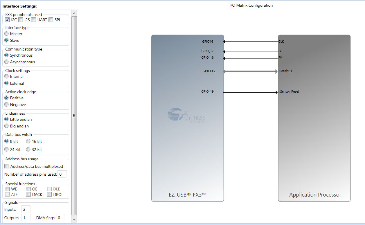
1. I wanted to use the AN75779 as it (except for changing LV, FV, nRST pin numbers in GPIF) is so I do not add any error to the original program. I interfaced it with a DeoNano FPGA board with a custom made interface board. I changed the pin numbers in GPIF accordingly. Please see GPIF interface definition picture attached. I use VLC to try to get some video. I wrote a test program in FPGA/verilog to generate the PCLK, LV, FV, DATA. I start with 8 bit DATA as in GPIF the original program it was 8 bit. Some Signaltap plots of FV, LV shown. I made it for 1280 x 720, 30FPS using PCLK of 48MHz. I added Frame and Line blanking accordingly so that the final frame rate is 30FPS. I uncommented the DEBUG_PRINT_FRAME_COUNT in uvc.h as per suggestion from other posts. But I always get Frame timer overflow and 0 frames and 0 buffers in the UART debug as attached. Is my idea/attempt wrong? I tried giving both longer and shorter blanking times keeping the 30FPS more or less same. If I manage to make this work, I hope I can make some progress to my actual project goal.
2. I am not using any I2C lines for now. Will this work without I2C connected? I guess so.
If I manage to get this FV, LV, Data test signal correctly, I will be making the actual readout in same sequence and timing hoping it to work fine. Later I will have to change the resolution too as I have one QVGA and one VGA sensors to be interfaced individually.
Thank you for your kind help.
Regards
Solved! Go to Solution.
- Mark as New
- Bookmark
- Subscribe
- Mute
- Subscribe to RSS Feed
- Permalink
- Report Inappropriate Content
Hemant,
After much of trial and error with the GPIF and UVC Descriptor file, and also I have resoldered the expansion headers. Now I am able to get the stream successfully. I have synchronized my video signal simulator part of my FPGA program and successfully streaming in exact resolution and frame rate. Now my next problem to solve is getting the 16-bit monochrome data. With 8 bit on GPIF, 16-bit definition on the UVC Descriptor, as expected, the streaming video is pink for a test pixel signal of 255 and green for a test pixel value of 0. I see 4 GUIDs are supported. What is the best way to solve this i.e., getting real 16-bit grayscale data on my PC for each pixel?