

- Mark as New
- Bookmark
- Subscribe
- Mute
- Subscribe to RSS Feed
- Permalink
- Report Inappropriate Content
Hi, I've referred AN75779 doc to accomplish that for our project.
Now, we want to change the transmission mechanism:
- FPGA will send out 2 type of data: image & info to FX3
- image data uses dual socket & info data use single socket to receive
- Use sw_pin to determine the type of the next incoming data
- Each HREF may receives different type of data(ex: HREF1 – image, HREF2 – info, HREF3 – image…)
- FPGA designs that each HREF data length is equal as the DMA buffer size(all are 8k)
Dummy state machine:

According to Getting Started doc, I've understood the mechanism for dual sockets yield:

The normal step behavior which use dual socket should like:

However, now, each HREF may receive different type of data. I worry it may cause Socket Linked List conflict...
Ex: HREF1 – image, HREF2 – info, HREF3 – image, HREF4 – image
My inference step behavior:
In the step 1, load the DMA Descriptor1 on socket1(thread1). However, the next image data is received by socket0, not the expected socket1.

Q1: Will it cause the conflict as the following fig and cause crash for USB transmission?

Q2: If the answer for Q1 is yes. Can I use the commands in FW to reset Socket Linked List to avoid the conflict?CyU3PDmaMultiChannelReset(&glChHandleSlFifoPtoU);
CyU3PDmaMultiChannelSetXfer(&glChHandleSlFifoPtoU, 0, 0);
CyU3PDmaMultiChannelSetXfer(&glChHandleSlFifoPtoU, 0, 1);
Thanks for your patience to read it. Any help will be highly appreciated!
Solved! Go to Solution.
- Labels:
-
USB Superspeed Peripherals
- Tags:
- fx3
- Mark as New
- Bookmark
- Subscribe
- Mute
- Subscribe to RSS Feed
- Permalink
- Report Inappropriate Content
Hello Hughes,
Ex: HREF1 - image, HREF2 - image, HREF3 - info, HREF4 - image
In this condition, it seems that your state machine isn't fit...
>> Yes, I had modified the state machine assuming the data format as Ex: HREF1 – image, HREF2 – info, HREF3 – image, HREF4 – image
Confirm again. If the condition is like the following fig, it may cause system error, right?
>> Yes, If the data is not written in PING PONG manner, then the error will occur. Once the DMA buffer associated to socket 0 is completely filled, the thread will switch and point to socket 1 and its associated buffer will be pointed. So it is expected to write to DMA buffer in ping pong format when two sockets are used as shown in the figure shared by you.
Q2: If the answer for Q1 is yes. I can require the FPGA to send out consecutive pair HREF - image without any HREF - info between the 2 HREF - image.
>> Yes, if the data format can be controlled from the FPGA then the new format, as below, will make GPIF state machine easier.
ex: HREF1 - image, HREF2 - image, HREF3 - info, HREF4 - image, HREF5 - image, HREF6 - info, HREF7 -
Rashi

- Mark as New
- Bookmark
- Subscribe
- Mute
- Subscribe to RSS Feed
- Permalink
- Report Inappropriate Content
Hello,
From the description, I understand that the data will always be coming in this pattern
Ex: HREF1 – image, HREF2 – info, HREF3 – image, HREF4 – image
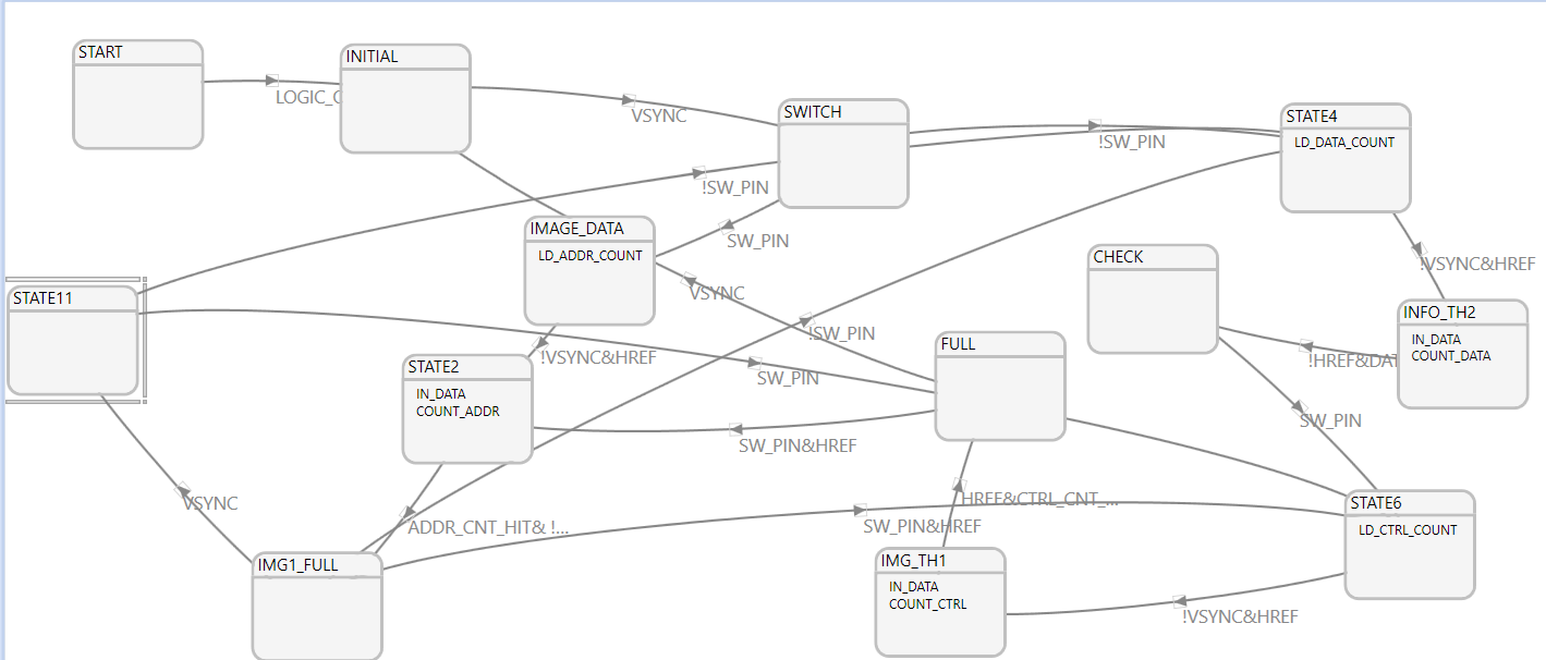
Please let me know why is the transition from INFO TH1 is made to switch. I have tried modifying the state machine so that the SMA buffers can be used in PING PONG manner. Please let me know if this helps (attached is the state machine)
Q1: Will it cause the conflict as the following fig and cause crash for USB transmission?
>> If the state machine that you shared is used, the HREF3 will again be written to TH0 instead of TH1 which will give an error.
Q2: If the answer for Q1 is yes. Can I use the commands in FW to reset Socket Linked List to avoid the conflict?
>> If DMA reset is done only one socket of the DMA channel will be used as data will only be written to TH0 and never written to TH1. Please try using the attached state machine and let me know if that helps.
Rashi
- Mark as New
- Bookmark
- Subscribe
- Mute
- Subscribe to RSS Feed
- Permalink
- Report Inappropriate Content
Dear Rashi:
Thanks for professional reply!
Ex: HREF1 – image, HREF2 – info, HREF3 – image, HREF4 – image
Please let me know why is the transition from INFO TH1 is made to switch. I have tried modifying the state machine so that the SMA buffers can be used in PING PONG manner. Please let me know if this helps (attached is the state machine)
I've studied the state machine you designed.
However, each HREF may send different data format.
Ex: HREF1 - image, HREF2 - image, HREF3 - info, HREF4 - image
In this condition, it seems that your state machine isn't fit...
>> If the state machine that you shared is used, the HREF3 will again be written to TH0 instead of TH1 which will give an error.
Q1: Let me to confirm again. If the condition is like the following fig, it may cause system error, right?

Q2: If the answer for Q1 is yes. I can require the FPGA to send out consecutive pair HREF - image without any HREF - info between the 2 HREF - image.
ex: HREF1 - image, HREF2 - image, HREF3 - info, HREF4 - image, HREF5 - image, HREF6 - info, HREF7 - info...
I think it could make me easier to design state machine, right?
PS.
>> If DMA reset is done only one socket of the DMA channel will be used as data will only be written to TH0 and never written to TH1.
I understand what you mean, thanks!
Best Regards,
Hughes
- Mark as New
- Bookmark
- Subscribe
- Mute
- Subscribe to RSS Feed
- Permalink
- Report Inappropriate Content
Hello Hughes,
Ex: HREF1 - image, HREF2 - image, HREF3 - info, HREF4 - image
In this condition, it seems that your state machine isn't fit...
>> Yes, I had modified the state machine assuming the data format as Ex: HREF1 – image, HREF2 – info, HREF3 – image, HREF4 – image
Confirm again. If the condition is like the following fig, it may cause system error, right?
>> Yes, If the data is not written in PING PONG manner, then the error will occur. Once the DMA buffer associated to socket 0 is completely filled, the thread will switch and point to socket 1 and its associated buffer will be pointed. So it is expected to write to DMA buffer in ping pong format when two sockets are used as shown in the figure shared by you.
Q2: If the answer for Q1 is yes. I can require the FPGA to send out consecutive pair HREF - image without any HREF - info between the 2 HREF - image.
>> Yes, if the data format can be controlled from the FPGA then the new format, as below, will make GPIF state machine easier.
ex: HREF1 - image, HREF2 - image, HREF3 - info, HREF4 - image, HREF5 - image, HREF6 - info, HREF7 -
Rashi