


- Mark as New
- Bookmark
- Subscribe
- Mute
- Subscribe to RSS Feed
- Permalink
- Report Inappropriate Content
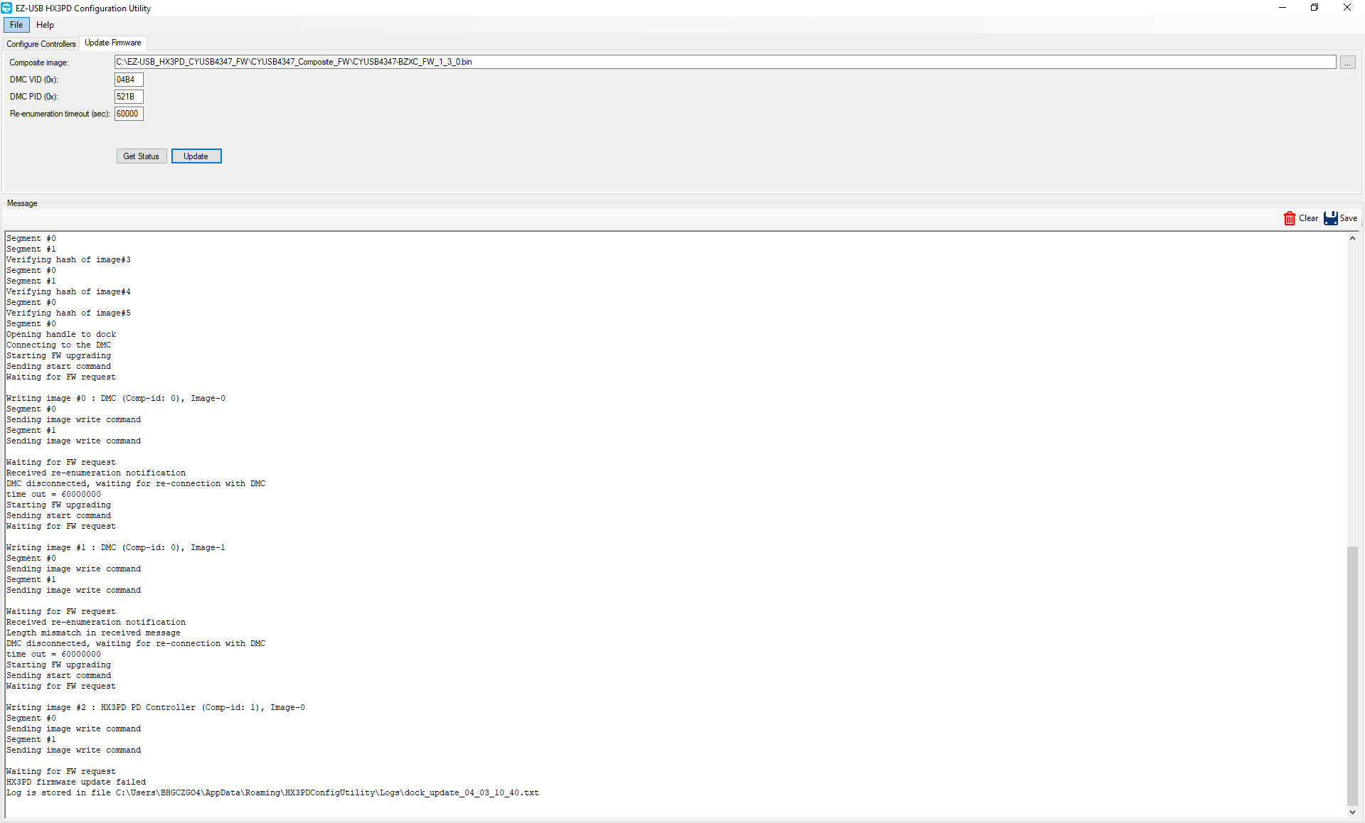
I have a total of 16 PWBs build of which two I am unable to program the CYUSB4357-BZXC. I checked all the supply voltages, chip selects , and so forth and everything seems okay. On one PWB, I've replace the flash and USB HUB twice and still can't program the USB HUB. Additionally the PWB was X-ray'd in that area and nothing out of the ordinary was observed. Via X-ray both the USB connector and transient protection devices seem soldered down properly. I'm not sure what to do next. What specific signals, voltages does the USB HUB need for programming? I included my design implementation and screen capture of the programming errors. What signals should I be concerned with? I did notice D+/D- levels appear to be transitioning logic low/logic high versus looking at a those signals on a working device where the levels are much faster and smaller (differential voltages).
Solved! Go to Solution.
- Mark as New
- Bookmark
- Subscribe
- Mute
- Subscribe to RSS Feed
- Permalink
- Report Inappropriate Content
Hello,
You would need to connect a MiniProg3/MiniProg4 to the SWD pins of DMC, PD controller and program using PSoC Programmer utility with target device chosen as HX3PD_DMC, HX3PD_PD. Please refer to the third FAQ in following KBA for detailed steps on SWD programming.
From the logs for your second board, it seems like the DMC didnt enumerate due to both the images being invalid.
Please try after updating the firmware on the boards over SWD and also a swap test between a working and non-working PWB.
If it still fails, kindly create a Failure Analysis case if you feel that the samples are not working as expected.
Best Regards,
Sananya