


- Mark as New
- Bookmark
- Subscribe
- Mute
- Subscribe to RSS Feed
- Permalink
- Report Inappropriate Content
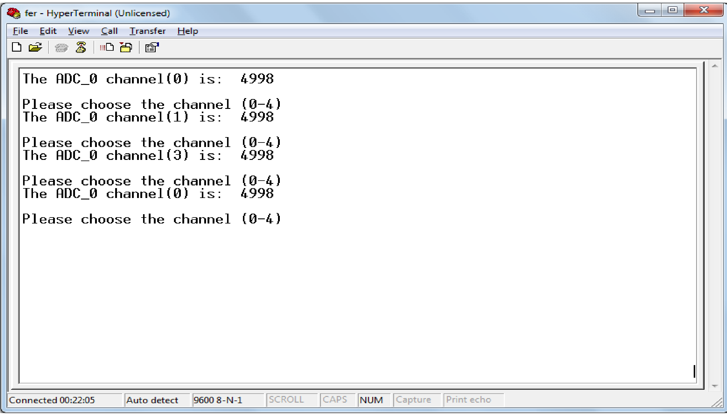
Can anyone tell me what the problem I have with CY8CKIT-050 to measure the voltage of a resistance of 10 k to 100 uA idac is not true and then varies the channels are 5 v without having connected to the resistor. How do I can find the true voltage?
- Labels:
-
PSoC 5LP
- Mark as New
- Bookmark
- Subscribe
- Mute
- Subscribe to RSS Feed
- Permalink
- Report Inappropriate Content
- Mark as New
- Bookmark
- Subscribe
- Mute
- Subscribe to RSS Feed
- Permalink
- Report Inappropriate Content
IDAC8 is a source current source, so it provides a constant current
sourced out of Vdda. In order for the current source to stay in the
constant current region it has to have a min voltage drop across it,
called compliance range. The compliance is 1V so for a 5V supply
the IDAC8 will operate over 0V to 4V, above 4V it will drop out of
regulation. So for 100 uA max R you can measure accurately is
4V / 1E-4 Amps = 40K.
The accuracy of IDAC8 is +/- 2.5%.
An analog mux, when its inputs are left floating, unconnected, will
exhibit anything from Vssa to Vdda depending on leakage.
In your code adcReading = ADC_SAR_0_GetResult16(); the API
returns a signed result, you need to change adcReading to int16,
not uint16 as it is now.
AMux_0_Start() disconnects all channels, you have to use the AMux_0_Select() or
AMux_0_Connect() API to connect a channel to the SAR ADC.
Regards, Dana
- Mark as New
- Bookmark
- Subscribe
- Mute
- Subscribe to RSS Feed
- Permalink
- Report Inappropriate Content
When you change the mux you should allow for a little settling time
for the analog signal to reach final value. You may have intrinsically
enough delay in your code / measurement loop, otherwise add some
delay. The delay cannot be easily computed, its impacted by IDAC8
settling time, mux Rdson, SAR input C and any stray C. The IDAC8
settles in ~ 125 nS, for a full scale step, see conditions in spec sheet.
Regards, Dana.
- Mark as New
- Bookmark
- Subscribe
- Mute
- Subscribe to RSS Feed
- Permalink
- Report Inappropriate Content
- Mark as New
- Bookmark
- Subscribe
- Mute
- Subscribe to RSS Feed
- Permalink
- Report Inappropriate Content
When I use Google Translate to translate spanish to english
I get unreadable result. Any chance you can post in english ?
/* Any value above 0x07 is an illegal input for mux channel selection */
#define ERROR_MASK (0x7Cu)
You are using the mux as differential, so the range of allowed channels
is 0 - 3.
When you connect mux to resistor you are connecting + input to junction of
IDAC and resistor, and - input to resistor ground ?
Right after you start mux you should issue a channel 0 select.
In the pinout view you do not have Vref external connected to a pin, should
be P0_4, and you apply a 5 V reference to it.
Regards, Dana.
- Mark as New
- Bookmark
- Subscribe
- Mute
- Subscribe to RSS Feed
- Permalink
- Report Inappropriate Content
yes, I connect mux to resistor you are connecting + input to junction of
IDAC and resistor, and - input to resistor ground and define ERROR_MASK (0x7Cu).
- Mark as New
- Bookmark
- Subscribe
- Mute
- Subscribe to RSS Feed
- Permalink
- Report Inappropriate Content
Another matter, when you use an external reference, your measurement
accuracy is determined by it. When you select input range with Vdd depend-
ence, the measurement is ratiometric to Vdd. That means your R measurement
will not be absolute accurate. Is that what you want ?
You are using differential measurement, but do you really need that in light of
IDAC8 accuracy only +/- 2%. You would stay with diff if you had high common
mode environment or poor grounds between Rx and PSOC or if distance was
large between Rx and PSOC, otherwise just use single ended.
I may be wrong but I would think you want internal reference, 0.0 ± 1.024V (Differential)
Input ± Vref If you do this then P0_4 would not be used. Also you would have to scale
IDAC to accomidate the A/D only measures 0 - 1.024 V.
- Mark as New
- Bookmark
- Subscribe
- Mute
- Subscribe to RSS Feed
- Permalink
- Report Inappropriate Content
I place 1.024V of internal reference and it send that value as a measure
- Mark as New
- Bookmark
- Subscribe
- Mute
- Subscribe to RSS Feed
- Permalink
- Report Inappropriate Content
IDAC8 100 uA thru a 10K resistor = 1 volt, so yes thats what you would measure.
Regards, Dana.
- Mark as New
- Bookmark
- Subscribe
- Mute
- Subscribe to RSS Feed
- Permalink
- Report Inappropriate Content
I place 5v of internal reference and it send that value as a measure 5v
- Mark as New
- Bookmark
- Subscribe
- Mute
- Subscribe to RSS Feed
- Permalink
- Report Inappropriate Content
I set up A/D a little different -
1) Set to continuous conversion.
2) Issued a
ADC_SAR_0_Start();
ADC_SAR_0_StartConvert();
outside for() loop. Removed StartConvert() inside start loop.
3) Set for Vref = 1.024, 0.0 ± 1.024V (Differential) Input ± Vref
4) Tried a 4.7K Rx and a 10K Rx and got 470 mV and 1000 mV, correct readings
5) Tried a Rx >> 10K (means > 1V) and readings turned negative as they were outside
measurement range.
6) You select the channel with this line of code AMux_0_Select(rdValue);
I monitored rdValue, and it was 209. That of course is wrong, rdValue can only range
from 0 to 3 because there are only 4 mux channels, so you have to fix that.
Regards, Dana.
- Mark as New
- Bookmark
- Subscribe
- Mute
- Subscribe to RSS Feed
- Permalink
- Report Inappropriate Content
it is AMUX that affects me, because without it; I have measured result very good
- Mark as New
- Bookmark
- Subscribe
- Mute
- Subscribe to RSS Feed
- Permalink
- Report Inappropriate Content
You make the following calculation -
rdValue = rdBuffer[0] - ASCII_DECIMAL_ZERO;
then issue a
AMux_0_Select(rdValue);
to select the mux channel. The mux channel only numbers 0 - 3,
for 4 differential channels. But if you place a breakpoint on the
AMux_0_Select(rdValue);
line you will see the rdValue is wacko, something > 200 ?
If rdBuffer[0] ever contains anything other than "0", "1", "2", "3" then you
will have a bad value that you will be using trying to select the mux
channel. Also when you do the calculation you have a mix of signed and
unsigned variables, then you operate on them as if they were signed.
Either change their definitions or cast them when you do the calculation.
rdValue = rdBuffer[0] - ASCII_DECIMAL_ZERO;
Regards, Dana.
- Mark as New
- Bookmark
- Subscribe
- Mute
- Subscribe to RSS Feed
- Permalink
- Report Inappropriate Content
I use a 1k resistor with current 100uA without AMUX . Measured exactly 100mV; but when I add the AMUX not give result.
- Mark as New
- Bookmark
- Subscribe
- Mute
- Subscribe to RSS Feed
- Permalink
- Report Inappropriate Content
My measuremnts doing what you did give the right results.
So take a voltmeter, place it on the pin and confirm you have 1V
for a 10K resistor. Place an additional pin on your schematic
tied to mux output, set a breakpoint 1 line of code after AMUX_Select( 0 ),
and see if that measures 1 V. If it does not then delete AMUX from schematic,
then place it again, and do a clean and build of project.
Otherwise I am stumped.
Regards, Dana.
- Mark as New
- Bookmark
- Subscribe
- Mute
- Subscribe to RSS Feed
- Permalink
- Report Inappropriate Content
- Mark as New
- Bookmark
- Subscribe
- Mute
- Subscribe to RSS Feed
- Permalink
- Report Inappropriate Content
usb no reconocido POR EL PC
- Mark as New
- Bookmark
- Subscribe
- Mute
- Subscribe to RSS Feed
- Permalink
- Report Inappropriate Content
Yes, I unconnected USB, just focused on getting the A/D and AMUX
working correctly. Just uncomment all the USB code lines and that
will restore your USB function.
Regards, Dana.
- Mark as New
- Bookmark
- Subscribe
- Mute
- Subscribe to RSS Feed
- Permalink
- Report Inappropriate Content
change to a ADC_SAR_Seq adc problem and gives me everything I measured not by s channels with AMUX gives me going problem with the other ADC.
- Mark as New
- Bookmark
- Subscribe
- Mute
- Subscribe to RSS Feed
- Permalink
- Report Inappropriate Content
int16 ADC_GetResult16(void) does not take a parameter, I think
you are thinking thats how you select channel. You do not need
the switch statements. All you need to do is change the mux channel
prior to conversion like I did in my version of your project that I posted.
So in the for loop where all the conversion and transmission is done,
increment a channel variable and use it in the AMUX_Seletc( channel variable )
just prior to the conversion by A/D. Dont forget to insert a small delay after mux change
to allow for setlling and to throw away 1 or 2 samples ( A/D is in continuous conversion).
Since you are running at 100000 SPS, delay for 20 - 30 uS should be good.
CyDelayUs( 30 );
Generally speaking always post you project archive, allows forum to look at entire picture
to help.
Regards, Dana.
Thats what I showed in