


- Mark as New
- Bookmark
- Subscribe
- Mute
- Subscribe to RSS Feed
- Permalink
- Report Inappropriate Content
I need to change SPI bus width in between 16 and 8 for different slave where can I do it is any smaple code that you can share
Regards
Albert
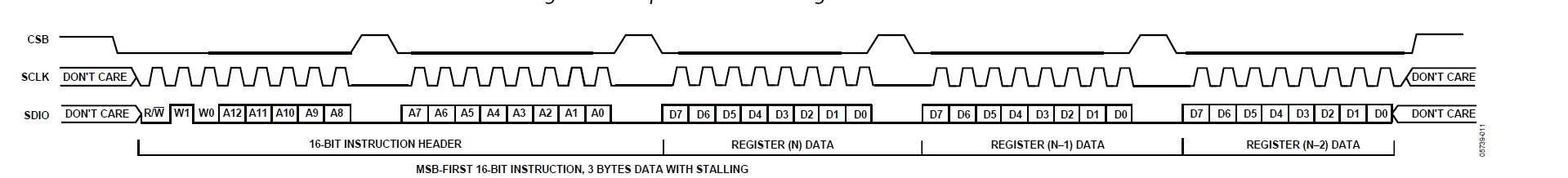
Message was edited by: Alberto Tello in the picture three bytes are written 0x80, 0x03, and 0x00 Why I have those glitches in MSB byte
Solved! Go to Solution.
- Mark as New
- Bookmark
- Subscribe
- Mute
- Subscribe to RSS Feed
- Permalink
- Report Inappropriate Content
Dear Albert-san,
So I tested with my CY8CKIT-059
schematic

pin assign

main.c
==================
#include "project.h"
#include <stdio.h>
char str[128] ;
void SPIM_Init_Width(uint8_t newWidth)
{
SPIM_DATA_WIDTH = newWidth ;
SPIM_BITCTR_INIT = (((uint8) (SPIM_DATA_WIDTH << 1u)) - 1u) ;
SPIM_Init() ;
}
void try_16bit(void)
{
uint16_t data16bit = 0xFACE ;
SPIM_Stop() ;
SPIM_Init_Width(16) ;
SPIM_Enable() ;
SPIM_WriteTxData(data16bit) ;
}
void try_8bit(void)
{
uint16_t data8bit = 0xA5 ;
uint16_t data16bit ;
data16bit = (data8bit << 😎 | 0x00 ; /* need a pad byte */
SPIM_Stop() ;
SPIM_Init_Width(8) ;
SPIM_Enable() ;
SPIM_WriteTxData(data16bit) ;
}
int main(void)
{
char str[64] ;
/* Enable Interrupts */
CyGlobalIntEnable;
UART_Start() ;
sprintf(str, "SPI Change Width Test (%s %s)\n", __DATE__, __TIME__) ;
UART_PutString(str) ;
/* Initializes the SPIM Component and all operations */
SPIM_Start();
while(1) {
LED_RED_Write(0) ;
try_16bit() ;
LED_RED_Write(1) ;
try_8bit() ;
CyDelay( 1000 );
} // while(1)
}
==================
I needed to modify 3 generated_sources, which is not recommended thing to do, though.
in SPIM.h
==================
// line 38
extern uint8_t SPIM_DATA_WIDTH ; /* moto */
// #define SPIM_DATA_WIDTH (16u)
// line 167
/* Nubmer of bits to receive/transmit */
// #define SPIM_BITCTR_INIT (((uint8) (SPIM_DATA_WIDTH << 1u)) - 1u)
extern uint8_t SPIM_BITCTR_INIT ; /* moto */
==================
in SPIM.c
==================
// line 39 added
uint8_t SPIM_DATA_WIDTH = (16u) ; /* moto */
uint8_t SPIM_BITCTR_INIT = (((uint8) (16 << 1u)) - 1u) ; /* moto */
==================
in SPIM_PM.c
==================
// line 23
// SPIM_BITCTR_INIT,
(((uint8) (16 << 1u)) - 1u), /* moto */
==================
When try_16bit() was called in main.c

When try_8bit() was called in main.c

Attached is "NOT" cleaned project, as generated_souce may be over written if cleaned.
Best Regards,
20-Aug-2019
Motoo Tanaka
P.S.
Once again, I wrote a stupid program.
また、つまらないプログラムを書いてしまった・・・
- Mark as New
- Bookmark
- Subscribe
- Mute
- Subscribe to RSS Feed
- Permalink
- Report Inappropriate Content
When the SS output is asserted, the MOSI/MISO is in unknown state. So, there may be a glitch.
But the glitch does not affect to the SPI protocol because the data on the MOSI/MISO is captured at next clock edge.

PSoC® Creator™ Component Datasheet
Serial Peripheral Interface (SPI) Master
Document Number: 001-96814

The parameter "Data Bits" on the component configuration Utility must be specified when the project is Built. The standard SPI Master component does not have any API to change the Data Bits in run time.
- Mark as New
- Bookmark
- Subscribe
- Mute
- Subscribe to RSS Feed
- Permalink
- Report Inappropriate Content
Hi,
This may be a kludge, but
In SPIM_Init(), there is a line
/* Initialize the Bit counter */
SPIM_COUNTER_PERIOD_REG = SPIM_BITCTR_INIT;
This SPIM_BITCTR_INIT is defined as
#define SPIM_BITCTR_INIT (((uint8) (SPIM_DATA_WIDTH << 1u)) - 1u)
And SPIM_DATA_WIDTH is defined as
#define SPIM_DATA_WIDTH (8u)
So, if you provide
SPIM_Init_with_width(uint8_t width)
which call
SPIM_COUNTER_PERIOD_REG = (((uint)(width << 1u)) - 1u)
and call it as
SPIM_Stop() ;
SPIM_Init_with_width(newWodth) ;
SPIM_Enable() ;
may take care of it.
Or may be we need to redefine SPIM_DATA_WIDTH as an external variable like
in SPIM.h
===============
// #define SPIM_DATA_WIDTH (8u)
extern uint8_t SPIM_DATA_WIDTH ;
===============
in your source file, such as main.c
================
uint8_t SPIM_DATA_WIDTH = 8u ;
===============
then before calling SPIM_Init() assining 8 or 16 may take care of it.
============
SPIM_Stop() ;
SPIM_DATA_WIDTH = newWidth ; // 8 or 16
SPIM_Init() ;
============
I wish Cypress has provided us SPIM_SetDataWidth(uint8_t newWidth) or something like that, though.
moto
- Mark as New
- Bookmark
- Subscribe
- Mute
- Subscribe to RSS Feed
- Permalink
- Report Inappropriate Content
The "NumberOfDataBits" parameter is passed to the B_SPI_Master sub-component in the SPI_Master component.

And the parameter is used in the Verilog description of the B_SPI_Master component like following.

Because the Verilog description specifies the UDB hardware configuration, it is unable to modify the bit width in run-time.
- Mark as New
- Bookmark
- Subscribe
- Mute
- Subscribe to RSS Feed
- Permalink
- Report Inappropriate Content
Dear Noriaki-san,
Thank you very much for your pointing out!
Then can't we define a 16-bit SPI and change the bit width to 8 when needed?
Best Regards,
19-Aug-2019
Motoo Tanaka
- Mark as New
- Bookmark
- Subscribe
- Mute
- Subscribe to RSS Feed
- Permalink
- Report Inappropriate Content
I am controlling the SS line manually when I try to set is Zero take long
time to go ZEro and vice versa how can i speed up this
Albert
On Mon, Aug 19, 2019 at 4:43 AM Motoo Tanaka <community-manager@cypress.com>
- Mark as New
- Bookmark
- Subscribe
- Mute
- Subscribe to RSS Feed
- Permalink
- Report Inappropriate Content
Dear Albert-san,
So I tested with my CY8CKIT-059
schematic
pin assign
main.c
==================
#include "project.h"
#include <stdio.h>
char str[128] ;
void SPIM_Init_Width(uint8_t newWidth)
{
SPIM_DATA_WIDTH = newWidth ;
SPIM_BITCTR_INIT = (((uint8) (SPIM_DATA_WIDTH << 1u)) - 1u) ;
SPIM_Init() ;
}
void try_16bit(void)
{
uint16_t data16bit = 0xFACE ;
SPIM_Stop() ;
SPIM_Init_Width(16) ;
SPIM_Enable() ;
SPIM_WriteTxData(data16bit) ;
}
void try_8bit(void)
{
uint16_t data8bit = 0xA5 ;
uint16_t data16bit ;
data16bit = (data8bit << 😎 | 0x00 ; /* need a pad byte */
SPIM_Stop() ;
SPIM_Init_Width(8) ;
SPIM_Enable() ;
SPIM_WriteTxData(data16bit) ;
}
int main(void)
{
char str[64] ;
/* Enable Interrupts */
CyGlobalIntEnable;
UART_Start() ;
sprintf(str, "SPI Change Width Test (%s %s)\n", __DATE__, __TIME__) ;
UART_PutString(str) ;
/* Initializes the SPIM Component and all operations */
SPIM_Start();
while(1) {
LED_RED_Write(0) ;
try_16bit() ;
LED_RED_Write(1) ;
try_8bit() ;
CyDelay( 1000 );
} // while(1)
}
==================
I needed to modify 3 generated_sources, which is not recommended thing to do, though.
in SPIM.h
==================
// line 38
extern uint8_t SPIM_DATA_WIDTH ; /* moto */
// #define SPIM_DATA_WIDTH (16u)
// line 167
/* Nubmer of bits to receive/transmit */
// #define SPIM_BITCTR_INIT (((uint8) (SPIM_DATA_WIDTH << 1u)) - 1u)
extern uint8_t SPIM_BITCTR_INIT ; /* moto */
==================
in SPIM.c
==================
// line 39 added
uint8_t SPIM_DATA_WIDTH = (16u) ; /* moto */
uint8_t SPIM_BITCTR_INIT = (((uint8) (16 << 1u)) - 1u) ; /* moto */
==================
in SPIM_PM.c
==================
// line 23
// SPIM_BITCTR_INIT,
(((uint8) (16 << 1u)) - 1u), /* moto */
==================
When try_16bit() was called in main.c
When try_8bit() was called in main.c
Attached is "NOT" cleaned project, as generated_souce may be over written if cleaned.
Best Regards,
20-Aug-2019
Motoo Tanaka
P.S.
Once again, I wrote a stupid program.
また、つまらないプログラムを書いてしまった・・・
- Mark as New
- Bookmark
- Subscribe
- Mute
- Subscribe to RSS Feed
- Permalink
- Report Inappropriate Content
Hi Motoo
I will implement your modifications ,
One more question MISO line which is an input , which of the following I
have to choose :
Strong Drive
High Impedance
Pull Down
or Pull up
I selected for MISO line strong drive
Regard
Albert
On Mon, Aug 19, 2019 at 5:57 PM Motoo Tanaka <community-manager@cypress.com>
- Mark as New
- Bookmark
- Subscribe
- Mute
- Subscribe to RSS Feed
- Permalink
- Report Inappropriate Content
Dear Albert-san,
The default setting was
High Impedance Digital

Best Regards,
21-Aug-2019
Motoo Tanaka
- Mark as New
- Bookmark
- Subscribe
- Mute
- Subscribe to RSS Feed
- Permalink
- Report Inappropriate Content
Motoo
Thank you for the information.
I have last question:
Wehe we use 8 bits I need to provide CLK high Stall <8 bits> CLK HIGH <8
bits>
With out controlling manually the clock high how can be set automatically
please the following pic:
Regards
Albert
On Tue, Aug 20, 2019 at 5:01 PM Motoo Tanaka <community-manager@cypress.com>
- Mark as New
- Bookmark
- Subscribe
- Mute
- Subscribe to RSS Feed
- Permalink
- Report Inappropriate Content
Dear Albert-san,
I think (hope) that you are talking about "MODE" of SPI.
We can switch logic of clock by changing CPHA in the Configure "SPIM"
The default is "CPHA = 0", with which SCLK is LOW between transaction.

If you change "CPHA = 1", then SCLK is HIGH between transaction.

Best Regards,
22-Aug-2019
Motoo Tanaka
- Mark as New
- Bookmark
- Subscribe
- Mute
- Subscribe to RSS Feed
- Permalink
- Report Inappropriate Content
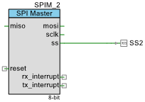
Hi Motoo
I have to control a device which has a mandatory SPI signals like whic
image is as follows
I setup one SPI2 to 8 bits CPHA=1 CPHOL =0,
Only one byte must be written and the SS line needs to go High as in the
above picture
The code Enable the following Interrupt flags:
SPIM_2_TX_STATUS_MASK_REG = ((uint8) (SPIM_2_STS_SPI_DONE ) /*|
(SPIM_2_STS_BYTE_COMPLETE )*/ );
Foe every SPI byte written SS must go High and when is written of course
must be go low ( The signal to follows is CBS )
Question enabling ((uint8) (SPIM_2_STS_SPI_DONE ) for th Interriupt SS
line will go High to Low automatically
This is correct How can I generate Autmatically signals SS ?
In the interrupt which I receive the correct number of interrupt the
code does
CY_SET_REG8(SPIM_2_TXDATA_PTR, (unsigned char)SPI_Buffer_wr[
Indx_wr++]); //next value
SPIM_2_TX_STATUS_MASK_REG &= ((uint8) ~SPIM_2_STS_SPI_DONE
);
Albert
- Mark as New
- Bookmark
- Subscribe
- Mute
- Subscribe to RSS Feed
- Permalink
- Report Inappropriate Content
Sorry Motoo
In the interrupt which I receive the correct number of interrupt the
code does
CY_SET_REG8(SPIM_2_TXDATA_PTR, (unsigned char)SPI_Buffer_wr[
Indx_wr++]); //next value
SPIM_2_TX_STATUS_MASK_REG |= ((uint8) (SPIM_2_STS_SPI_DONE
); CORRECT VALUE IN THE INTERRUPT HANDLE *
Albert
On Mon, Aug 26, 2019 at 10:59 AM Alberto Tello <alberto@illusense.com>
- Mark as New
- Bookmark
- Subscribe
- Mute
- Subscribe to RSS Feed
- Permalink
- Report Inappropriate Content
Dear Albert-san,
I think that you are starting a new kind of question.
I hope that for the "sPI change data width" I have already showed you one possible solution,
there may/must be many more possible approaches, though.
And it is preferable to have one-question and one-answer for each topic/discussion in the community, so that later others can locate the problem and the questions easily.
So would you please create a new discussion with appropriate tile for this question?
Best Regards,
27-Aug-2019
Motoo Tanaka
- Mark as New
- Bookmark
- Subscribe
- Mute
- Subscribe to RSS Feed
- Permalink
- Report Inappropriate Content
Hi Motoo
Thank you for the info ,
But i am still having problem with the glitch problem .
I am sending three bytes 0x80, 0x03, 0x00; in order to read same
devices, if you see the pic is a glitch in the first byte.
Note: SS is set manually , before the first data is write to :
CY_SET_REG16(SPIM_1_TXDATA_PTR, SPI_Buffer_wr[Indx_wr++]);
In the interrupt we read each value
Where can be the mistake
Albert
On Mon, Aug 19, 2019 at 1:32 AM Noriaki Tanaka <