

PSoC™ 5, 3 & 1 Forum Discussions
Especially thanks to motoo tanaka for testing out my basic test program. I simplified the test program even more, but still get compiler failure. This time I just took exactly what you wrote, but left out the printing part. The following is a copy, including the error messages. This should work. I just don't understand.
#include "project.h"
#include "math.h"
double A=1.0;
double B=1.0;
uint8_t n ;
int main(void)
{
for(;;)
{
for (n = 1 ; n <= 10 ; n++)
{
B = exp(5.0 / n) ;
if (n == 10)
{
A = 1.0 ;
B = 1.0 ;
}
}
} *****this is the line number 22 that the error message refers to
}
/* [] END OF FILE */
ERROR MESSAGE ARE AS FOLLOWS
OK. So the messages I get are as follows:
"collect2.exe: error: ld returned 1 exit status"
It also said " The command 'arm-none-eabi-gcc.exe' failed with exit code '1'. "
It also said this in the notice list
"build error: undefined reference to 'exp' line 22" (I marked line 22 so you could see what they were referring to. Don't know how to copy the listing with line numbers included)
So how come this fails to compile ? Such a simple program. As before, using psoc5lp board and creator version 3.3
Show Less


I've come across a perplexing problem. I have a CY8CKIT-059 and using PSOC Creator 4.3. I have a Programmable Gain Amplifier (PGA) with a gain of 2, and the reference set to external, and attached to a Vref component. With the Vref component set to Vdda/2, the reference voltage will actually change when I change the input voltage to the PGA. When the input votlage is zero, the voltage from the VREF component will read 1.4 V, and it increases tp 3.4 V when the PGA input is near 5V. This does not happen with any of the other reference voltage options (1.024 V, Vdda etc). Does anyone have any insights into this problem?
Show LessHello everyone
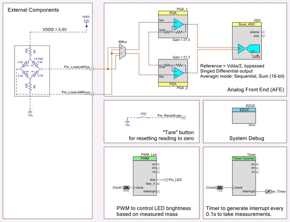
It's my first topic on this forum and I need help with a project that I have.
I bought the PSOC 5LP kit aiming to design a weight scale after reading about the 20 bit sigma delta ADC and PGA integrated.
My weight scale is composed by a 20 kg load cell with 2mv/V rated output and the PSOC 5LP. I will also use only 2/3 of the full range of the cell to preserve linearity.
I'm running into a weird issue with using the PSoC5LP I2C Bootloader Interface.
I am using a CY8C5467LTI-LP003. Building my project in PSoC Creator Version 4.2.
I am performing the bootload operation with a custom C# .NET application using bootl_utils.dll (built from the source from Creator 4.1 if I'm remembering right), that interfaces with the CY7C65211A (I2C Vendor Driver) via cyusbserial.dll.
I should note that I have modified the bootloader utilities library that I'm using here, as I detailed here in this old thread where I was also having problems bootloading over I2C.
I can see nothing wrong with the operation of the host, it looks to be sending the correct packets in the correct format, but the data coming back from the PSoC appears to be the issue. Particularly with the response to the "Program Row" command. See the logic capture below:

Note the response from the PSoC5, it looks like it's stretching the clock for some reason when its address is called out after receiving the 0x39 (Program Row) command packet. It actually looks like it forms a correct response, but the first byte of the packet is wrong (0xFF). It's a little tough to see, but the bytes in the response on the stretched read are as follows:
FF-01-00-00-00-FF-FF
This is interesting, because judging from previous responses, the packet SHOULD be:
01-00-00-00-FF-FF-17
It looks like it's sending the correct number of bytes, and that it assembles the packet, but for some reason is sneaking an 0xFF into the first byte rather than the 0x01 Start of Packet byte, and pushing out the 0x17 End of Packet byte. I image
I am logging all I2C in and out in the log window of my bootloader application, here's the complete Command/Response history leading up to the failure:
W: 01-38-00-00-C7-FF-17
R: 01-00-08-00-69-30-10-2E-00-3C-01-01-E2-FE-17
W: 01-33-01-00-00-CB-FF-17
R: 01-05-00-00-FA-FF-17-FF-FF
W: 01-32-01-00-00-CC-FF-17
R: 01-00-04-00-15-00-FF-00-E7-FE-17
W: 01-37-39-00-00-40-00-20-11-15-00-00-51-1E-00-00-51-1E-00-00-08-B5-00-F0-BD-FC-00-00-10-B5-05-4C-23-78-33-B9-04-4B-13-B1-04-48-AF-F3-00-80-01-23-23-70-10-BD-48-C1-FF-1F-00-00-00-00-88-74-F0-17
R: 01-00-00-00-FF-FF-17
W: 01-37-39-00-46-00-00-08-4B-10-B5-1B-B1-08-49-08-48-AF-F3-00-80-08-48-03-68-03-B9-10-BD-07-4B-00-2B-FB-D0-BD-E8-10-40-18-47-00-BF-00-00-00-00-4C-C1-FF-1F-88-46-00-00-C8-C0-FF-1F-00-00-64-ED-17
R: 01-00-00-00-FF-FF-17
W: 01-37-39-00-00-00-80-B5-9A-B0-62-B6-02-F0-AB-F9-02-F0-BF-F9-02-F0-F9-F8-02-F0-45-F9-02-21-00-20-01-F0-27-F9-00-F0-D9-FC-85-4C-00-F0-01-02-D3-B2-22-70-00-F0-1E-02-04-2A-0D-D0-02-D8-02-BA-E5-17
R: 01-00-00-00-FF-FF-17
W: 01-37-39-00-2A-05-D0-27-E0-08-2A-0E-D0-10-2A-13-D0-22-E0-00-22-62-70-FB-B1-7B-4A-13-E0-01-22-62-70-0B-B9-7A-4A-0E-E0-7A-4A-0C-E0-02-22-62-70-0B-B9-78-4A-07-E0-78-4A-05-E0-03-22-62-70-E6-EA-17
R: 01-00-00-00-FF-FF-17
W: 01-37-39-00-0B-B9-77-4A-00-E0-77-4A-13-78-03-F0-F1-03-43-F0-08-03-13-70-13-78-43-F0-01-03-13-70-01-45-00-40-01-4F-00-40-07-52-00-40-09-64-00-40-02-65-00-40-15-00-01-40-37-01-01-40-58-C7-F1-17
R: 01-00-00-00-FF-FF-17
W: 01-39-06-00-00-15-00-02-01-40-68-FF-17
R: FF-01-00-00-00-FF-FF
W: 01-3B-00-00-C4-FF-17
It also looks like the response to the Get Application Status (0x33) command is a little funky, with 2 extra 0xFF bytes tacked on the end, but this doesn't seem to be causing any problem in the process.
The problem appears to be on the PSoC side, but I was also able to successfully load using the Bootloader Host included with creator using the MiniProg3 as my USB-I2C bridge, so there's evidence pointing to both ends being the culprit?
Might anyone have an idea as to what's going on?
Thanks in advance for any tips!
Show Less我现有用3866芯片做了一个我别的单片机进行CAN通信的功能,目前可以确定我3866的硬件没有问题,因为这板子和ARM 通信没有问题,现在要和一个新的单片机做CAN通信,现在另外一个单片机发出来的信号用试波器在总线量有信号了,在3866的接收脚上量也有信号了,但是3866的的这个中断进不了。
请问一般是什么原因造成的。谢谢

Hi to all!
The PSoC® Creator™ System Reference Guide, Document Number: 001-94480, Rev. ** (page 97) states:
"The CySysResetReason() function can be used to detect if the watchdog has triggered device reset"
It seems to me that this function does not exist!
The component data sheet mentions support for multiple Report ID’s, but outside of the device configuration variables (USBFS_DEVICEx_CONFIGURATIONx_INTERFACEx_ALTERNATEx_HID_FEATURE_BUF_IDx/RPT_SCB_IDx), I can't find specific information on how to handle this. I would like to know if each report ID has a corresponding custom report handler (which could be user defined) linked to an interrupt vector table, or if the only immediate interrupt available is via the IN/OUT endpoints of the USB, at which point we would check the Report ID.
Any clarification regarding this would be much appreciated!
Thank you.
Mike Roberts
Show Less Solved
Change the PGA gain by calling PGA_SetGain () in the program.
How long does it take to complete the switch
プログラム内で PGA_SetGain() をCALLして PGAのゲインを変更します。
切り替え完了までの時間は どの程度必要でしょうか
Show LessDear Cypress community,
I want to software-reset my device at a certain point and provide a custom reset cause (which can be used as a flag for a part of the initialization code). My idea was to use RESET_SR0: 0x400046FA or CYREG_PHUB_CFGMEM23_CFG1: 0x400076BC for this because bit 4 (0x10) seems to be unused. The code I wrote to do this is simple:
void sw_reset_with_custom_reset_cause() {
uint8 currentValue = CY_GET_REG8(CYREG_RESET_SR0);
currentValue |= 0x10;
CY_SET_REG8 (CYREG_RESET_SR0, currentValue);
CySoftwareReset();
}
The problem is that it does not work as expected (reset cause is always 0x20 after calling the SW reset). My hope would of course be to get a reset cause that is equal to 0x30. I've tried with both above mentioned registers but with no luck.
What am I doing wrong here?
Best regards,
Sander
Show Less