

- Mark as New
- Bookmark
- Subscribe
- Mute
- Subscribe to RSS Feed
- Permalink
- Report Inappropriate Content
hi to all,
how can i set reference voltage for ADC in psoc1. here i want to set reference voltage 2.5v.
thanks
PRP
Solved! Go to Solution.
- Labels:
-
PSoC 1
- Mark as New
- Bookmark
- Subscribe
- Mute
- Subscribe to RSS Feed
- Permalink
- Report Inappropriate Content
Also look in TRM (Technical Reference Manual) for your device to get a better
understanding of the Ref system.
Regards, Dana.

- Mark as New
- Bookmark
- Subscribe
- Mute
- Subscribe to RSS Feed
- Permalink
- Report Inappropriate Content
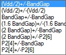
In global resouces window, upper left corner, select "Ref Mux" and
pick one of attached selections. Note if you are using Vdd = 5V, then
Vdd/2 +/- Vdd/2 is a 2.5 Volt reference. If you are 3.3V Vdd then use
external reference, or route external to a PGA and set its gain to get
a 2.5 V Ref.
Regards, Dana.
- Mark as New
- Bookmark
- Subscribe
- Mute
- Subscribe to RSS Feed
- Permalink
- Report Inappropriate Content
Also look in TRM (Technical Reference Manual) for your device to get a better
understanding of the Ref system.
Regards, Dana.
- Mark as New
- Bookmark
- Subscribe
- Mute
- Subscribe to RSS Feed
- Permalink
- Report Inappropriate Content
Also, refer application note AN2219 PSoC 1 selecting analog ground and reference
http://www.cypress.com/?rID=2779
-Rajiv Badiger
- Mark as New
- Bookmark
- Subscribe
- Mute
- Subscribe to RSS Feed
- Permalink
- Report Inappropriate Content
Hi every body!
When I use ADC10 user module to measure DC voltage 0-4V, it is OK (I'm using CY8C21323, PSoC designer 5.4). I want measure 0-5V, can you please tell me solution for that?
Thanks!
- Mark as New
- Bookmark
- Subscribe
- Mute
- Subscribe to RSS Feed
- Permalink
- Report Inappropriate Content
Simplest method is external R V divider, as PGA is not available on
this part. Divider would scale 0 - 5 to 0 - 4. Of course it would affect
loading of signal, and you would have to trade off magnitude of R's
for offsets due to leakage. And ratio would require hi accuracy R's
if you want to maintain accuracy. A signal path error analysis would
be in order.
Regards, Dana.
- Mark as New
- Bookmark
- Subscribe
- Mute
- Subscribe to RSS Feed
- Permalink
- Report Inappropriate Content
Hi every body,
This is next question, can you help me?
I'm doing project with PSoC CY8C21323, PSoC designer 5.4.
Contents:
PSoC measure DC voltage (0-5V) from 4 pin (AnalogInput):
- P0.3 : voltage 0-5V.
- P0.2: voltage of LM35.
- P0.4: voltage of current sensor return (2.5-5V).
- P0.6: voltage of voltage sensor return(0-5V).
PSoC send all data to PC via RS232 circuit, using TX8 module.
At PSoC CY8C21323, in ADCs module, i see only ADC10 (has 2 analog column, AnalogColumn_InputMUX_1 and AnalogColumn_InputMUX_0).
How to get data from 4 pin AnalogInput? By ADC10? ADC10 can measure 0-4V!!!
(At PSoC CY8C21323: no ADCINC, ADCINCVR,DELSIG,PGA...)
Many thanks!
- Mark as New
- Bookmark
- Subscribe
- Mute
- Subscribe to RSS Feed
- Permalink
- Report Inappropriate Content
Put the ADC into the right column (01) and use an AMUX8. Then you may select ANY input from port0
Bob
- Mark as New
- Bookmark
- Subscribe
- Mute
- Subscribe to RSS Feed
- Permalink
- Report Inappropriate Content
Hi Dana,
If without external RV divider, have you another solution to measure 0-5V? By another user module?
Because i don't want change circuit which I did.
Thanks!
- Mark as New
- Bookmark
- Subscribe
- Mute
- Subscribe to RSS Feed
- Permalink
- Report Inappropriate Content
Hi Bob,
I will do that you said.
Thanks!
- Mark as New
- Bookmark
- Subscribe
- Mute
- Subscribe to RSS Feed
- Permalink
- Report Inappropriate Content
Yes, you could use a 16 bit PWM as a DAC, feed that to a comparator,
the other side comparator Vx from AMUX. In code do a binary search on
PWM duty cycle (compare) value to trip the comparator (poiling its output)
, or use ISR on it.
This will take 1 analog and 2 digital blocks, unless you use 8 bit PWM (1 block),
which equates to ~ 40 mV ADC resolution.
Note PWM has LP filter on output to create a DC value proportional to duty
cycle of PWM. PWM filter controls settling time, ripple, attached might be of help.
Regards, Dana.
- Mark as New
- Bookmark
- Subscribe
- Mute
- Subscribe to RSS Feed
- Permalink
- Report Inappropriate Content
Hi Bob, Dana
I have just coded project, i'm using TX8, ADC10, AMUX8 user module.
(refer "Measure and Display 0 to 4 V on LCD Using ADC10"; www.cypress.com/?docID=35081).
PSoC measure DC voltage (0-5V) from 4 pin (AnalogInput):
- P0.3 : voltage 0-5V.
- P0.2: voltage of LM35.
- P0.4: voltage of current sensor return (2.5-5V).
- P0.6: voltage of voltage sensor return(0-5V).
-P1.3: TX8.
PSoC send all data to PC via RS232 circuit, using TX8 module.
(Currently, set voltage input for 4 pin AnalogInput 0-4V to test)
But built project errors:
Linking..
!E <library>(1539): {linker} area 'text' not large enough. Need 932 bytes
lo 3897 hi 4095 size 199
!E ftoa.s(1435): {linker} Code address 0:0x151 already contains a value
!E ftoa.s(1435): {linker} Code address 0:0x152 already contains a value
!E ftoa.s(1435): {linker} Code address 0:0x153 already contains a value
!E ftoa.s(1435): {linker} Code address 0:0x154 already contains a value
!E ftoa.s(1435): {linker} Code address 0:0x156 already contains a value
!E ftoa.s(1435): {linker} Code address 0:0x157 already contains a value
!E ftoa.s(1435): {linker} Code address 0:0x159 already contains a value
!E ftoa.s(1435): {linker} Code address 0:0x15a already contains a value
!E ftoa.s(1435): {linker} Code address 0:0x15c already contains a value
!E ftoa.s(1435): {linker} Code address 0:0x15d already contains a value
!E ftoa.s(1437): {linker} Code address 0:0x15c already contains a value
!E ftoa.s(1437): {linker} Code address 0:0x15d already contains a value
!E ftoa.s(1437): {linker} Code address 0:0x15e already contains a value
{linker} Too many errors, exiting...
make: *** [output/CY8C21323_ADC_0_5V.rom] Error -1
!W Use Code Compression Technologies at Projects -> Settings -> Compiler to improve memory utilization
CY8C21323_ADC_0_5V - 15 error(s) 1 warning(s) 22:42:57
I don't why! My project has about 100 line of code. Can you tell me, please? This is my project!
Thanks!
- Mark as New
- Bookmark
- Subscribe
- Mute
- Subscribe to RSS Feed
- Permalink
- Report Inappropriate Content
Your ftoa is eating up 40% of your flash. Better think of calculating in integer arithmetic and convert yourself (inserting dec-point at the correct position)
Having only 4K flash is a bit challenging...
Bob
- Mark as New
- Bookmark
- Subscribe
- Mute
- Subscribe to RSS Feed
- Permalink
- Report Inappropriate Content
Here is one possibility for your own C ftoa() -
http://www.geeksforgeeks.org/convert-floating-point-number-string/
Just google "C ftoa" and there are others.
Regards, Dana.
- Mark as New
- Bookmark
- Subscribe
- Mute
- Subscribe to RSS Feed
- Permalink
- Report Inappropriate Content
Hi Bob, Dana
Because ftoa() is eating up 40% of your flash which Dana said. So I don't convert recieved data from 4 pin AnalogInput to voltage, I only read value ADC10 returns from 4 pin. But value ADC10 which i received is "-", you don't care oC, A,V,Next; these are text. I'm using itoa() in project; check data by terminal 1.9b.
- oC - A - V - V Next...
- oC A - V - V Next...
- oC - A - V - V Next...
I think: prolems at select pin AnalogInput by AMUX8 module fail, so ADC10 can't work well.
Can you please check configuration, code in my project? Is it correct?
Many thanks. This is my project!
- Mark as New
- Bookmark
- Subscribe
- Mute
- Subscribe to RSS Feed
- Permalink
- Report Inappropriate Content
Not all of your used inputs on port0 are defined as AnalogInputs- Check the pin-configuration.
Bob
- Mark as New
- Bookmark
- Subscribe
- Mute
- Subscribe to RSS Feed
- Permalink
- Report Inappropriate Content
In parts such as this code space precious. Some suggestions to mimimize
needed code size -
These helped me in a similar experience -
1 - If any float math minimize the number of lines you do divides, if possible convert
to multiplies. Convert float to integer math where possible. Pay attention to factoring
of expressions, possible operation reduction, hence code reduction may result.
2 - Lines with function calls, minimize f(g()) compound typed expressions.
3 - Make sure you only use a variable type no larger than needed.
4 - Use unsigned variables wherever possible.
5 - Watchout for structures with mixed const and ram pointers within them,
some compilers choke on this.
6 - If you are heavy on Flash, light on RAM use, convert routines to RAM based
wherever possible.
7 - Try test cases of looping structures, to see what affects code size generation.
8 - Examine .lst file for code that looks wacky in bytes used, understand what
compiler did, and consider rewrite.
9 - Use inline ASM where .lst file C generation looks excessive.
10 - Look at module reuse, sharing, dual purpose, to eliminate # modules
needed, like counters/timers....Also look at data sheets of modules that could
serve function needed, and compare ROM/RAM requirements needed. Optimize
global HW, like clocks VC1/2/3/Sleep, to eliminate need for other timer/counters.
Use register routing control to "share" module from one task to another, one pin
to another.
11 - Extended library, functions within them are written to be perfectly general,
hence larger code size, you may be able to write one with less code needed for
your specific requirements that result in smaller code size.
12 – Look for approximations to compute transcendental functions if used.
13 - Although no longer supported by HiTech or Cypress, the HiTech Pro compiler
yielded on first try ~ 40% code reduction in my design when I first converted
to it. Then the prior comments yielded another 4 K later in design as I was up
against 32 K Flash limitation.
14 - Some compilers have a setting to optimize code size or speed, the latter
prone to larger code size. Also look at compiler vendors web site for ap notes
and suggestions on optimization, compilers from different vendors behave and
optimize differently.
15 - const data, strings, etc.., look for ability to reuse common string mnemonics,
text.
16 - Pointer usage can lessen code size, see url's below. Look for function calls
passing longs as value vs pointer, convert to latter. Compiler has to copy all these,
if not referenced. Do not pass longs or floats as values, keep always in mind native machine size.
17 - Most compilers will optimize when indexes, pointers, a power of 2, or divides,
divide becomes a shift.
18 - Look at how linker distributed code and data segments, sometimes you can discover
a poor decision by linker and force code/data into certain psects using pragma constructs,
thereby minimizing wasted ROM space.
19 – When you debug generally you want to turn off optimization, as compiler/linker will
remove code and make jumps that do not make “sense” but are the result of optimization.
When you are up to Flash boundary you may not be able to turn it off, otherwise
application will not load. Keep this in mind, that your debug strategy may have to change.
I also found if using ICE Cube that debugger may no longer report “watch” variables, this
occurred at ~ 31.5K bytes. In either case you may want to comment out large code sections
to effectively debug.
20 – f() calls take overhead, if you only call a f() once you might eliminate it as a f() call and
place code inline.
21 – Look for f() opportunities, wherever you are coding and repeating similar operations.
This is obvious, but sometimes missed.
22 – Check compiler on macros, to see if they are being optimized or just being used inline
using more code space vs a f() call solution.
23 – Examine compiler/linker parameter control. For example in HiTech there is the AUTOBANK
setting that controls where local variables are stored, in my case setting to 1 lowered code size by
~ 250 bytes. READ the MANUAL !
24 – Use inline variable declarations, vs pre declaration (compiler dependent) -
This void dosomething ( void ) {
for ( unsigned char I = 0;…..
}
Not This void dosomething ( void ) {
Unsigned char I = 0;
for ( I = 0;…..
}
Some help -
http://www.codeproject.com/Articles/6154/Writing-Efficient-C-and-C-Code-Optimization
http://www.eventhelix.com/realtimemantra/basics/optimizingcandcppcode.htm
http://www.azillionmonkeys.com/qed/optimize.html
By using these techniques I was able to regain ~ 4K Bytes of code space in a 32K design, which
I promptly then used up again 😞
Note HiTech compiler, no longer offered, but if you can get a copy I experienced a 40% code
reduction over Imagecraft. And > 30% over Imagcraft Pro.
Regards, Dana.
- Mark as New
- Bookmark
- Subscribe
- Mute
- Subscribe to RSS Feed
- Permalink
- Report Inappropriate Content
Thanks Bob, Dana!
Hi Bob, you said:
"Not all of your used inputs on port0 are defined as AnalogInputs- Check the pin-configuration."
Mean:
If all of inputs on port0 must be defined as AnalogInputs, I would use AMUX8 module.
Currently, on port0, i'm using 4 pin as AnalogInputs, not enough to use AMUX8 module?
Can you please tell me why?
Thanks!
- Mark as New
- Bookmark
- Subscribe
- Mute
- Subscribe to RSS Feed
- Permalink
- Report Inappropriate Content
Sorry Bob 
I understand that you said after checking configuration pin in my project!
Thanks for your help!
- Mark as New
- Bookmark
- Subscribe
- Mute
- Subscribe to RSS Feed
- Permalink
- Report Inappropriate Content
Any pin used as analog must be set to "AnalogInput", "Hi Z Analog".
So if you used AMUX4 those pins and any other pins in the port, used
as analog, must be set per above.
Regards, Dana.
- Mark as New
- Bookmark
- Subscribe
- Mute
- Subscribe to RSS Feed
- Permalink
- Report Inappropriate Content
Hi Dana,
I have solved problems about convert float to string.
I will code for measuring voltage 0-5V (CY8C21323).
If i have problems, i will ask you again.

Many thanks!
- Mark as New
- Bookmark
- Subscribe
- Mute
- Subscribe to RSS Feed
- Permalink
- Report Inappropriate Content
Hi Dana,
I read document which you sent for me, but I can't understand clearly about "Using PWM16 and AMUX user module to measure voltage 0-5V" ( your another solution).
At PSoC CY8C21323: no ADCINC, ADCINCVR,DELSIG,PGA... So I'm difficult to solve that prolem!
Can you tell me clearly, please?
Or can you send a project example about that for me?
Many thanks.
- Mark as New
- Bookmark
- Subscribe
- Mute
- Subscribe to RSS Feed
- Permalink
- Report Inappropriate Content
Use a PWM and a comparator wired as shown below. Then write
a SAR like routine that works as follows (the binary search algorithim
in this ap note) http://www.maximintegrated.com/en/app-notes/index.mvp/id/1080
Simply stated you start by setting all bits of the compare value of PWM, which sets its
duty cycle, to 0 except for MSB, if the comparator then outputs a 0 then voltage is less
and this compare bit gets set to 0, otherwise leave it, then set MSB - 1 bit to "1" and
look at comparator output again after writing this to PWM compare register. As you go
thru this simple algorithim you will arrive at an equivalent voltage out of the PWM
integrator that ~ matches Vunknownin, eg. the last comapare value you used for PWM.
The reference is Vdd in this approach, which controls accuracy. If you need high
accuracy use a reference for Vdd for the PSOC. The other issue is the approach relies
on the input signals varing slowly, otherwise algorithim will produce a bad result. Real
world SARs use a S/H on their input. In your case use averaging to eliminate the
varience for rapid input signal changes. Stated another way the algorithim ideally would
like to run faster that the input signal rate of change for 1/2 LSB.
The PWM filter, you trade off settling time vs ripple, the app note I attached earlier will aid in
determining its cutoff frequency.

- Mark as New
- Bookmark
- Subscribe
- Mute
- Subscribe to RSS Feed
- Permalink
- Report Inappropriate Content
Another approach is to use simple RC, and this ap note discusses that
and simple slope converters you can consider.
http://www.ti.com/lit/an/snoa627/snoa627.pdf
Regards, Dana.
- Mark as New
- Bookmark
- Subscribe
- Mute
- Subscribe to RSS Feed
- Permalink
- Report Inappropriate Content
One more method, you have to make calculations for input
range. Try googling this problem for simple A to D with embedded
processors, I am sure there are other ideas out there.
http://www.bytecraft.com/Low_Cost,_Low_Speed_A_D_conversion_for_Embedded_Systems
Regards, Dana.
- Mark as New
- Bookmark
- Subscribe
- Mute
- Subscribe to RSS Feed
- Permalink
- Report Inappropriate Content
Hi Bob, Dana
I have issue when I select pin AnalogInPut for ADC10 by AMUX8.
It's:
- I want: select pin0.x by AMUX8, ADC10 will return value pin0.x
- Actual: select pin0.x by AMUX8, ADC10 will return not value pin0.x!!!
Although, that value returns is correct! I checked on the circuit!
Pin AnalogInput in my project:
P0.2: LM35
P0.4: I
P0.6: Vaq
P0.3: Vvr
//This is results if I call true pin on the circuit, it isn't value which I want (Line of code is commented by me):
Unit: V (voltage)
LM35= 02.95; I= 00.44; Vaq = 02.46; Vvr = 03.91
LM35= 02.96; I= 00.44; Vaq = 02.47; Vvr = 03.91
...
LM35: P0.3 return (Vvr) , not P0.2 return
I: P0.2 return (LM35), not P0.4 return
Vaq: P0.4 return (I), not P0.6 return
Vvr: P0.6 return (Vaq), not P0.3 return
I can't why???
//This is results if I call not true pin on the circuit, but that value which I want!(Line of code is not commented):
LM35= 00.44; I= 02.53; Vaq = 03.98; Vvr = 03.00
LM35= 00.44; I= 02.53; Vaq = 03.89; Vvr = 03.02
...
With
LM35: I called P0.4
I: I called P0.6
Vaq: I called P0.3
Vvr: I called P0.2
Here is code funtion select pin AnalogInput:
unsigned int ReadADCChannel(BYTE Channel)
{
unsigned int ADCResult;
BYTE x;
AMUX8_Start();
switch (Channel)
{
case 0:
// Connect P0.2 to Mux Bus
// AMUX8_InputSelect(AMUX8_PORT0_2);
AMUX8_InputSelect(AMUX8_PORT0_4);
break;
case 1:
// Connect P0.4 to Mux Bus
// AMUX8_InputSelect(AMUX8_PORT0_4);
AMUX8_InputSelect(AMUX8_PORT0_6);
break;
case 2:
// Connect P0.6 to Mux Bus
// AMUX8_InputSelect(AMUX8_PORT0_6);
AMUX8_InputSelect(AMUX8_PORT0_3);
break;
case 3:
// Connect P0.3 to Mux Bus
// AMUX8_InputSelect(AMUX8_PORT0_3);
AMUX8_InputSelect(AMUX8_PORT0_2);
break;
}
// Give a small delay
for (x = 0; x < 25; x++) {};
while(0 == ADC10_fIsDataAvailable());
ADCResult = ADC10_iGetDataClearFlag();
ADC10_ClearFlag();
AMUX8_Stop();
// Return the result
return ADCResult;
}
Below, there is my project!
Can you check for me, please?
Many thanks!
- Mark as New
- Bookmark
- Subscribe
- Mute
- Subscribe to RSS Feed
- Permalink
- Report Inappropriate Content
I can't see the problem unless you have wired pins wrong. Below is what your
project says the wiring is, and I commented up your code a little -
unsigned int ReadADCChannel(BYTE Channel)
{
unsigned int ADCResult;
BYTE x;
AMUX8_Start();
switch (Channel)
{
case 0: // Temperature
// Connect P0.2 to Mux Bus
// AMUX8_InputSelect(AMUX8_PORT0_2); // Temperature
AMUX8_InputSelect(AMUX8_PORT0_4); // Current
break;
case 1: // Current
// Connect P0.4 to Mux Bus
// AMUX8_InputSelect(AMUX8_PORT0_4); // Current
AMUX8_InputSelect(AMUX8_PORT0_6); // Voltage
break;
case 2: // Voltage
// Connect P0.6 to Mux Bus
// AMUX8_InputSelect(AMUX8_PORT0_6); // Voltage
AMUX8_InputSelect(AMUX8_PORT0_3); // 5V
break;
case 3: // 5V
// Connect P0.3 to Mux Bus
// AMUX8_InputSelect(AMUX8_PORT0_3); // 5V
AMUX8_InputSelect(AMUX8_PORT0_2); // Temperature
break;
}
- Mark as New
- Bookmark
- Subscribe
- Mute
- Subscribe to RSS Feed
- Permalink
- Report Inappropriate Content
Possibly this is problem, maybe do a clean and build on design, reaching for straws.
http://www.cypress.com/?id=4&rID=93824
Regards, Dana.
- Mark as New
- Bookmark
- Subscribe
- Mute
- Subscribe to RSS Feed
- Permalink
- Report Inappropriate Content
Thanks Dana,
I will do that you said!
- Mark as New
- Bookmark
- Subscribe
- Mute
- Subscribe to RSS Feed
- Permalink
- Report Inappropriate Content
Hi Dana,
I did that you advise buy it isn't success!
I removed AMUX8. Then I used AMUX4 but it isn't success same when I use AMUX8.
(About: select pin0.x by AMUX8, ADC10 will return not value pin0.x!!! ; at PSoC CY8C21323)
I think it is prolem with AMUX4/AMUX8.
Currently, I have a pin on PSoC CY8C21323: P1.2 (can't configure as AnalogInput. So I can't use ADC10).
P1.2 (input): Signal ipnut is analog.
If P1.2 have signal input , voltage on P1.2 is : 0 - 3.84V.
If P1.2 have no signal input , voltage on P1.2 is 4.8V.
I want compare voltage value on P1.2 with 3.84V (check status on pin P1.2, ON/OFF).
- (voltage value on P1.2) < 3.84V: ON (have signal input).
- (voltage value on P1.2) > 3.84V: OFF(no signal input).
Can you help me, please?
What are user modules that check status on pin P1.2?
Many thanks!
- Mark as New
- Bookmark
- Subscribe
- Mute
- Subscribe to RSS Feed
- Permalink
- Report Inappropriate Content
Can you take just 1 pin, configured as analog in, hi z analog, and feed
a voltage to it into ADC10 and get correct result ?
To read a pin, if it is a digital input, use vpin = PRTnDR where n = port
number. Note if this is in a port where you are doing read modify writes
you must use shadow registers, see this topic in -
http://www.cypress.com/?rID=2900
Post project again in current state. Note I do not have the hardware to test
your project, so you might consider posting a CASE at cypress where then
can setup and run your basic code and verify any issues.
To create a technical case at Cypress -
“Support”
“Technical Support”
“Create a Case”
You have to be registered on Cypress web site first.
Regards, Dana.
- Mark as New
- Bookmark
- Subscribe
- Mute
- Subscribe to RSS Feed
- Permalink
- Report Inappropriate Content
If you want to check V on a pin, 3.84 V -
1) Place a CMP (Comparator module)
2) Positive input to analog mux buss, and route pin to it
3) Negative input to VBG (internal reference 1.3V)
4) On pin to mux buss to CMP place a R divider At pin so that its junction = 1.3 V when
input to the divider = 3.84 V
5) Config pin as analog in, hi z analog.
5) Poll the comparator output with API or use ISR (look at notes in datasheet on
interrupt generation control). If you want to poll, you would add a digital buffer, route its input
to comparator buss, and its output to a pin, and poll the pin.
Regards, Dana.
- Mark as New
- Bookmark
- Subscribe
- Mute
- Subscribe to RSS Feed
- Permalink
- Report Inappropriate Content
- Mark as New
- Bookmark
- Subscribe
- Mute
- Subscribe to RSS Feed
- Permalink
- Report Inappropriate Content
Hi Dana,
About "Can you take just 1 pin, configured as analog in, hi z analog, and feed
a voltage to it into ADC10 and get correct result ?".
if I take just 1 pin, ADC10 return value correct; no problem!
I will see those topic which you advise.
Thanks!
- Mark as New
- Bookmark
- Subscribe
- Mute
- Subscribe to RSS Feed
- Permalink
- Report Inappropriate Content
Hi Bob, Dana
I'm doing a project with PSoC1 CY8C24123A.
Contents:
- Measure voltage on P0.3, P0.2, P0.4 (0-5V).
- Then, send all data (voltage) to PC (via RS232 circuit).
I'm using user modules: ADCINCVR, PGA,AMUX8,TX8.
If I measure voltage only pin (example P0.3), it's OK (ADCINCVR, PGA,TX8).
But when I measure 3 that pin, values are not correct!(ADCINCVR, PGA,AMUX8,TX8). Voltage on 3 pin is similar(equals)!
Can you check my project ,please? Or tell me another solutions to do that project!
Below is my project!
Many thanks!
- Mark as New
- Bookmark
- Subscribe
- Mute
- Subscribe to RSS Feed
- Permalink
- Report Inappropriate Content
Post the latest copy of your project.
Regards, Dana.
- Mark as New
- Bookmark
- Subscribe
- Mute
- Subscribe to RSS Feed
- Permalink
- Report Inappropriate Content
- Mark as New
- Bookmark
- Subscribe
- Mute
- Subscribe to RSS Feed
- Permalink
- Report Inappropriate Content
Your pins at P0 are not set as "Analog Input"
Bob
- Mark as New
- Bookmark
- Subscribe
- Mute
- Subscribe to RSS Feed
- Permalink
- Report Inappropriate Content
Ooops, sorry 
Bob
- Mark as New
- Bookmark
- Subscribe
- Mute
- Subscribe to RSS Feed
- Permalink
- Report Inappropriate Content
There and back again!
You use P0_2 _4 _6 _3 and only of those P0_3 is an analog input port.
Bob