


- Mark as New
- Bookmark
- Subscribe
- Mute
- Subscribe to RSS Feed
- Permalink
- Report Inappropriate Content
Hi,
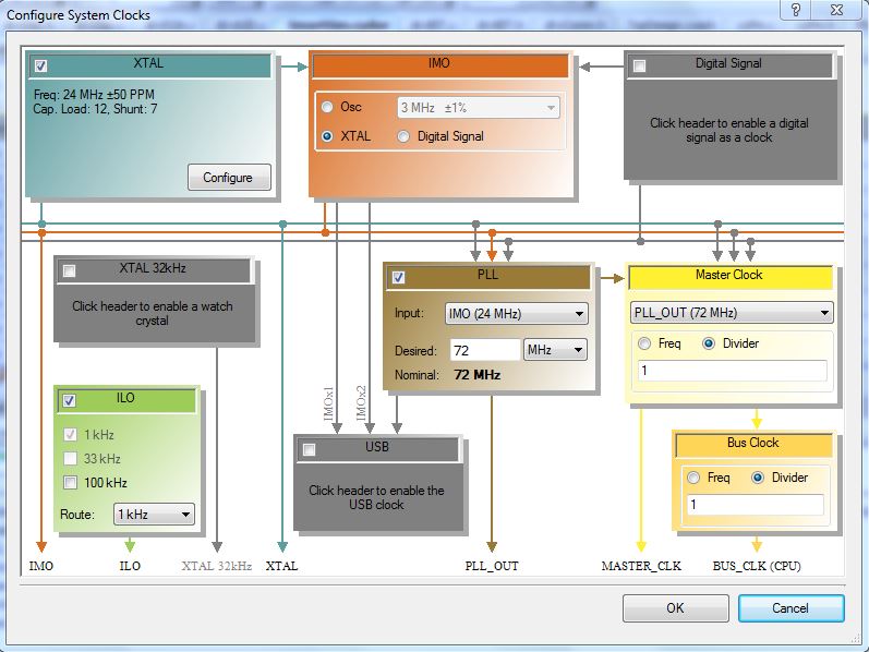
I'm having a difficult time with changing my PSoC's CPU clock (bus clock) to 72MHz.
I followed the instructions, but I still get this error: Warning-1366: Setup time violation found in a path from clock ( CyBUS_CLK ) to clock ( CyBUS_CLK ).
I attached few screenshots so you can understand more easily the problem.
P.S.
I won't be able to upload the project.
Solved! Go to Solution.
- Mark as New
- Bookmark
- Subscribe
- Mute
- Subscribe to RSS Feed
- Permalink
- Report Inappropriate Content
Thanks.
First, you seem to use an older version of PSoC Creator. I'm using 4.1, and have updated all components of your project to their current versions.
After, building, I get two timing warnings.
One is for FreeRunTimer, and is important. A 24.bit UDB timer can run with at most 28MHz according to the data sheet, but your using a 75MHz clock.
Second is for PWM_Out, and is because its reset signal comes from a control register, which in turn is clocked by MASTER_CLK. Setting the control registers to sync mode, and using a common 10kHz clock helps (the one which clocks the PWM itself).
Next the UARTa problems come up. I synced the clock lines to the same 10kHz clock, and the muxes too.
Remember: any signal coming from a control register is effectively in the MASTER_CLK domain. So it introduces signal at this frequency to all attached components (even via muxes, since you can e.g. switch the signal in the middle of a clock cycle)
The remaining problem is the rx_3 inout. Probably because its going through a mux it also needs to be synced to a slower clock. (Although setting the pin to 'transparent' helped).
- Mark as New
- Bookmark
- Subscribe
- Mute
- Subscribe to RSS Feed
- Permalink
- Report Inappropriate Content
"Setup time violation" usually means that you clock a component too fast. The error message shows what the maximum frequency is you can use, given the clock dividers / components use.
Verify the clock frequencyies for all components you are using against their data sheet.
- Mark as New
- Bookmark
- Subscribe
- Mute
- Subscribe to RSS Feed
- Permalink
- Report Inappropriate Content
Thanks for the answer.
I have checked all the clocks. I did notice the maximum frequency message. But it is very weird due to the fact that the cpu max frequency is 80 MHz and not 40 something .
- Mark as New
- Bookmark
- Subscribe
- Mute
- Subscribe to RSS Feed
- Permalink
- Report Inappropriate Content
You still can clock the CPU with 72 or 80 MHz. But you cannot clock all of the UDBs with that frequency.
The timing report actually should show you, further down, where this problems happens and which components are affected.
- Mark as New
- Bookmark
- Subscribe
- Mute
- Subscribe to RSS Feed
- Permalink
- Report Inappropriate Content
But as you can see the error refers to bus clk, which is the clock I want to change to 72 MHz.
Isnt it? Am I missing something here?
- Mark as New
- Bookmark
- Subscribe
- Mute
- Subscribe to RSS Feed
- Permalink
- Report Inappropriate Content
The problem is somewhere between BUS_CLK and MASTER_CLK - which means a component referring both (for one or the other reason). Without further details from your timing report or your project its impossible to tell. Try to upload your project (or a small sample project which has the affected component in it)
- Mark as New
- Bookmark
- Subscribe
- Mute
- Subscribe to RSS Feed
- Permalink
- Report Inappropriate Content
matans,
There are several steps to remedy timing violation problem. Read this CY App Note describing various issues arising from clock skew, particular the section "Using the PSoC Creator STA Report":
PSoC® 3, PSoC 4, and PSoC 5LP Digital Design Best Practices
What is likely happened, you have large amount of logic elements in PLD section (schematic / Verilog etc.), which is not running in CPU or UDB clock domains, and thus slowing BUS_CLOCK.
1. Try to add clock Sync component in places where CPU and PLD domains intersect.
2. In Design Wide Resources -> System -> Operatin temperature range change from (-20C to 85C) to (0C to 85C). This will easy constrains on the design.
3. Having a timing violation warning is unpleasant, but design may still work (with some dficiencies, and maybe not in entire temperature range specified). If project is not critical, this may suffice.
odissey1
- Mark as New
- Bookmark
- Subscribe
- Mute
- Subscribe to RSS Feed
- Permalink
- Report Inappropriate Content
Hi,
Thanks again for you kind help.
I'm attaching three more screenshots. Two of the schematic design, and the other one is the static timing analysis.
I think it will help you to help me with this problem (thanks again!).
One more thing about this warning: Setup time violation found in a path from clock ( CyBUS_CLK ) to clock ( CyBUS_CLK ).
what does CyBUS_CLK to CyBUS_CLK means? how can there be a time violation between one clock to it self?
Thanks.


- Mark as New
- Bookmark
- Subscribe
- Mute
- Subscribe to RSS Feed
- Permalink
- Report Inappropriate Content
Can you please upload the project so we can have a look at the exact configurations? If it has sensitive stuff in it, create a sample project exposing the problem.
My assumption for now: the MUXes are clocked by the BUS_CLK. This means your clock input into the UARTs also depends on the BUS_CLK (independent of the clock signal you are switching). The maximum allowed input clock for a simple UART is 46MHz.
You might try:
- sync the switched clock signal to a e.g. 32MHz clock
- use a clock component whose divider you change at runtime
- or keep the counter solution you already have, but make it an 8bit counter, and just re-define its period at runtime
No need to use a mux for selecting a baud rate.
- Mark as New
- Bookmark
- Subscribe
- Mute
- Subscribe to RSS Feed
- Permalink
- Report Inappropriate Content
- Mark as New
- Bookmark
- Subscribe
- Mute
- Subscribe to RSS Feed
- Permalink
- Report Inappropriate Content
Thanks.
First, you seem to use an older version of PSoC Creator. I'm using 4.1, and have updated all components of your project to their current versions.
After, building, I get two timing warnings.
One is for FreeRunTimer, and is important. A 24.bit UDB timer can run with at most 28MHz according to the data sheet, but your using a 75MHz clock.
Second is for PWM_Out, and is because its reset signal comes from a control register, which in turn is clocked by MASTER_CLK. Setting the control registers to sync mode, and using a common 10kHz clock helps (the one which clocks the PWM itself).
Next the UARTa problems come up. I synced the clock lines to the same 10kHz clock, and the muxes too.
Remember: any signal coming from a control register is effectively in the MASTER_CLK domain. So it introduces signal at this frequency to all attached components (even via muxes, since you can e.g. switch the signal in the middle of a clock cycle)
The remaining problem is the rx_3 inout. Probably because its going through a mux it also needs to be synced to a slower clock. (Although setting the pin to 'transparent' helped).
- Mark as New
- Bookmark
- Subscribe
- Mute
- Subscribe to RSS Feed
- Permalink
- Report Inappropriate Content
Thank you for your kind answer.
I saw you synced all the UARTs clock with 10kHz clock, but if I want to work in higher rate (as you saw the mux outputs can be also 115200)
won't it be a problem?
- Mark as New
- Bookmark
- Subscribe
- Mute
- Subscribe to RSS Feed
- Permalink
- Report Inappropriate Content
There should not be a problem with that. The reason I used a 10kHz clock was that the number of different clocks you can have in your design is limited, and you are using already quite some for the baud rates (which you should change to use only one, as already suggested).
When you get timing errors, take a look at the detail information for the particular warning. It tells you which components are forming the critical path, sou you can find out where you need to sync into a lower frequency domain.