


- Mark as New
- Bookmark
- Subscribe
- Mute
- Subscribe to RSS Feed
- Permalink
- Report Inappropriate Content
Hello,
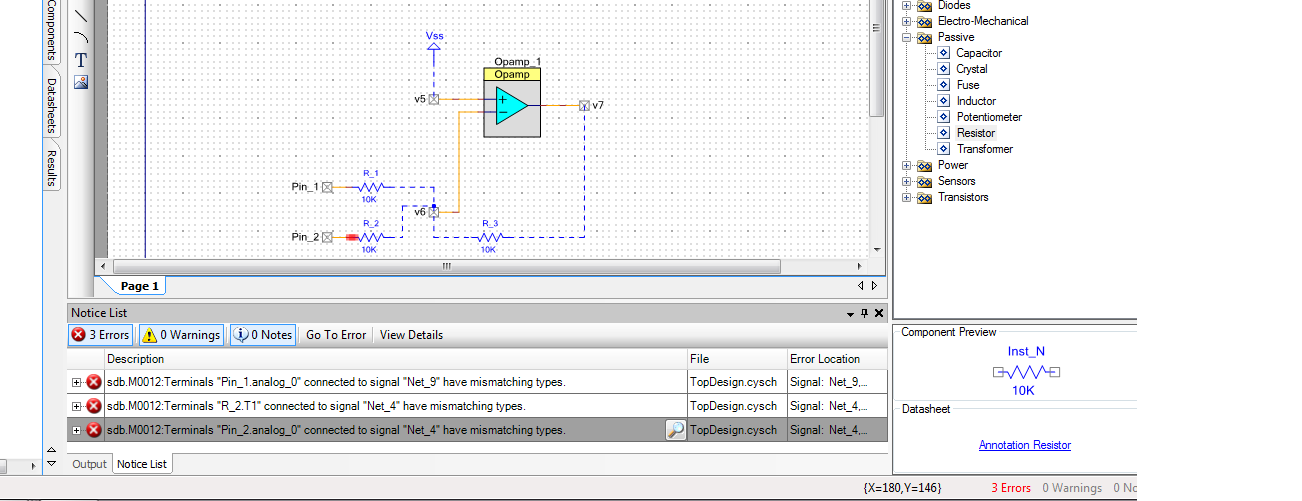
i am trying to work opamp as "adder" (adding two analog signals with different frreq) ,but i am facing some errors in connecting resistors to the analog input pins. Please say how to avoid this.
I have shown the schematic diagram and errors in pic
- Labels:
-
PSoC 3
- Mark as New
- Bookmark
- Subscribe
- Mute
- Subscribe to RSS Feed
- Permalink
- Report Inappropriate Content
You did not connect your resistors to the annotation-terminal of the pin_1 and pin_2 and the pins are not connected to any wires in the PSoC.
Bob
- Mark as New
- Bookmark
- Subscribe
- Mute
- Subscribe to RSS Feed
- Permalink
- Report Inappropriate Content
If you view the "notice" list after a compile you can double click most error
notices and the error will be highlighted on schematic so that you can easily
identify and correct it.
Regards, Dana,
- Mark as New
- Bookmark
- Subscribe
- Mute
- Subscribe to RSS Feed
- Permalink
- Report Inappropriate Content
- Mark as New
- Bookmark
- Subscribe
- Mute
- Subscribe to RSS Feed
- Permalink
- Report Inappropriate Content
Well, the message states exactly what the situation is: the pin is unconnected.
You are mistaking the "inner" side and the "outer" side of the PSoC: The OpAmp is within the PSoc, all blue components and lines are outsides of the PSoC, so probably you do not need pin_1 and pin_2 and connect your signals to be added directly to your external resistors.
Bob
- Mark as New
- Bookmark
- Subscribe
- Mute
- Subscribe to RSS Feed
- Permalink
- Report Inappropriate Content
It means the resistors which are in the PSoC creator doesn't like resistors in the circuit???
should i connect resistors externally also?
- Mark as New
- Bookmark
- Subscribe
- Mute
- Subscribe to RSS Feed
- Permalink
- Report Inappropriate Content
You have got the resistors from the "Annotation" tab in the components window, these are NOT resistors within the PSoC, they are used to clarify / document the external connections of your PSoC design.
You will have to provide these resistors in reality and connect them to your pins and your signals.
Draw a line, everything that is blue is not within your PSoC chip and has to be connected externally.
Bob
- Mark as New
- Bookmark
- Subscribe
- Mute
- Subscribe to RSS Feed
- Permalink
- Report Inappropriate Content
- Mark as New
- Bookmark
- Subscribe
- Mute
- Subscribe to RSS Feed
- Permalink
- Report Inappropriate Content
Your Vref wants to be Vdd/2 or an internal (bandgap) derived Vref (some multiple therof)
in order to maximize OpAmp output swing and place it in its CM range.
Regards, Dana.
- Mark as New
- Bookmark
- Subscribe
- Mute
- Subscribe to RSS Feed
- Permalink
- Report Inappropriate Content
- Mark as New
- Bookmark
- Subscribe
- Mute
- Subscribe to RSS Feed
- Permalink
- Report Inappropriate Content
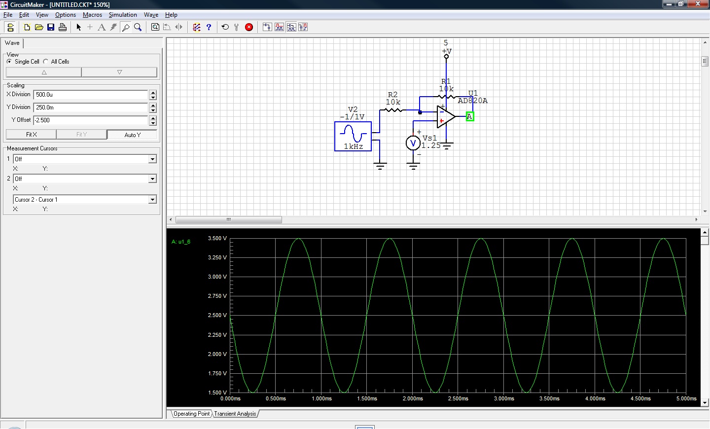
Hello,
My schematic diagram is shown in Pic,In that I am adding two signals ,to get the correct output of “OPAMP” I should give some offset to the input signals,here output of OPAMP also producing some offset. If I give this output of OPAMP(with some offset) to the ADC I won’t get correct output.
Should I always use some level shifters for every output of a component???
- Mark as New
- Bookmark
- Subscribe
- Mute
- Subscribe to RSS Feed
- Permalink
- Report Inappropriate Content
You have to offset the OpAmp so that your swing will produce
an allowed CM range swing on output. Thats if your input is
symmetrical about ground.
If you input is always - then you may not need offset. Or
for all + input signals you do not care OpAmp output is fixed
at ground, you are only measuring - input signals.
All analog components must have their input CM range met, normally
one level shift at the signal input accomplishes that.
The example I showed in previous post is for a signal whose input
is symmetrical about ground.
Regards, Dana.