

- Mark as New
- Bookmark
- Subscribe
- Mute
- Subscribe to RSS Feed
- Permalink
- Report Inappropriate Content
I want to create a 0-100uA constant current pulse with 20V compliance for use as biological stimulation device. I was originally planning to use a VDAC and an external voltage-controled current source to generate the current pulse. I then thought about simply using an iDAC and current mirror, but i've never used a current mirror. I think that the
Do you guys think the iDAC + current mirror would be a better choice than the VDAC + current converter?
- Labels:
-
PSoC 3
- Mark as New
- Bookmark
- Subscribe
- Mute
- Subscribe to RSS Feed
- Permalink
- Report Inappropriate Content
I used that method in the past do get increased dynamic range in a
LV situation, 3.3V operation, and was very effective at removing the
complience issues on the input side of the mirror. In your case you
also get the HV ability on the output side of the current mirror. The
obvious challenges are transistor matching, linearity, etc.....
Sink mirrors easiest, source a little more challenging because of the effects
of Vdd, or high side reference effects on mirror equations.
There is a lot of info on web, just goggle "current mirror design", you
will be reading well into the next century.
Regards, Dana.
- Mark as New
- Bookmark
- Subscribe
- Mute
- Subscribe to RSS Feed
- Permalink
- Report Inappropriate Content
As far as topology, one of the simplest looks like -
You should do an error analysis to see if your goals are met.
Regards, Dana.
- Mark as New
- Bookmark
- Subscribe
- Mute
- Subscribe to RSS Feed
- Permalink
- Report Inappropriate Content
A good reference on mirrors -
http://highered.mcgraw-hill.com/sites/dl/free/0070601623/337358/jae20990_ch16.pdf
Regards, Dana.

- Mark as New
- Bookmark
- Subscribe
- Mute
- Subscribe to RSS Feed
- Permalink
- Report Inappropriate Content
Thanks for the info. I'm aware of transitor matching issues, but I am currently find an integrated current mirror IC. Don't know if that will help.
The images you posted are similar to my voltage controled current source (see pic). However I can't seem to choose the correct transistor. All my simulations are failing when my load gets above above a certain point, but within voltage compliance.
Also, I'm considering usinga switching scheme or current steering scheme to change current direction withing the load. That will allow me to use one topology.
Would you prefer the VDAC + voltage controled current source over the iDAC + current mirror solution?
- Mark as New
- Bookmark
- Subscribe
- Mute
- Subscribe to RSS Feed
- Permalink
- Report Inappropriate Content
My inclination would be to use IDAC with a Wilson current mirror.

http://en.wikipedia.org/wiki/Wilson_current_mirror
Regards, Dana.
- Mark as New
- Bookmark
- Subscribe
- Mute
- Subscribe to RSS Feed
- Permalink
- Report Inappropriate Content
Hello,
I am trying to achieve something similar for a DC application: 0~100 uA with ~20V compliance voltage. For the suggested Wilson current mirror below, how should the iDAC be connected. Are there any specific BJT models to recommend?

- Mark as New
- Bookmark
- Subscribe
- Mute
- Subscribe to RSS Feed
- Permalink
- Report Inappropriate Content
What components would you choose to implement that solution? I'd like to use IDAC with a minimum of ceremony to stimulate brain slices but I don't know what's available... Cheers
- Mark as New
- Bookmark
- Subscribe
- Mute
- Subscribe to RSS Feed
- Permalink
- Report Inappropriate Content
In the wilson current mirror shown Q1 and Q2 would like to be
matched. ON Semi and Fairchild have matched transistor pairs
that make this easy. Pretty much all with Vcesus > 20 V.
Regards, Dana.
- Mark as New
- Bookmark
- Subscribe
- Mute
- Subscribe to RSS Feed
- Permalink
- Report Inappropriate Content
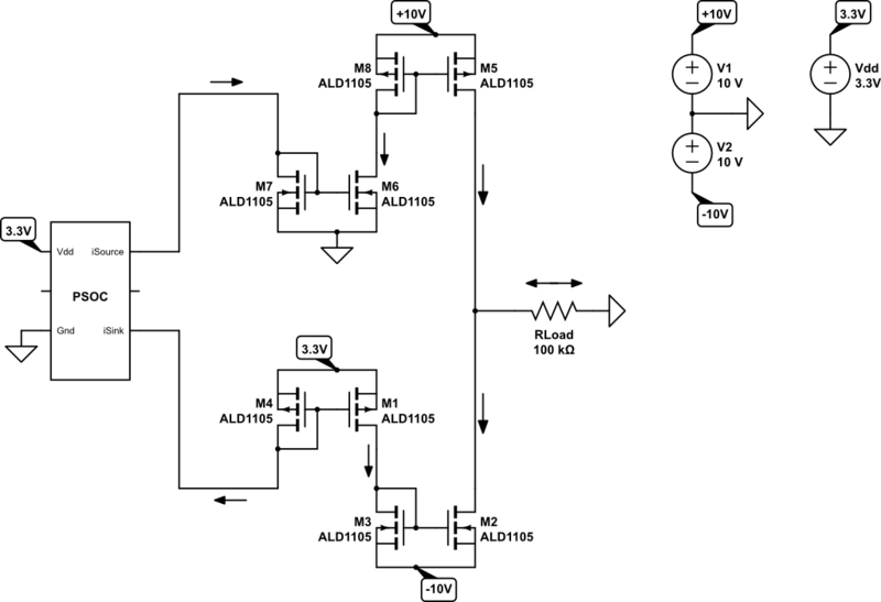
Ok. I'm back the the current mirror problems. 🙂 I've has some success using the opamp solutions that dana posted. I would like eliminate the need for any opamp and use a wilson or cascoded current mirror with an IDAC as the reference current. My application requrires that I use a + and -12V referenced to gnd as seen in the attached images. I can only get the current sink design with P-mosfets to work only if I use 3.3V as the common voltage and not 12V.
Question: How can I impliment a 12V source and sink current mirror using the internal IDAC (see image) ?
FYI: Here's a good artical with some useful IDAC info: http://www.cypress.com/?docID=42985
- Mark as New
- Bookmark
- Subscribe
- Mute
- Subscribe to RSS Feed
- Permalink
- Report Inappropriate Content
Not sure that the image imported correctly. Here it is again.
- Mark as New
- Bookmark
- Subscribe
- Mute
- Subscribe to RSS Feed
- Permalink
- Report Inappropriate Content
Last try with the image. Please read above post to help me answer my question.

- Mark as New
- Bookmark
- Subscribe
- Mute
- Subscribe to RSS Feed
- Permalink
- Report Inappropriate Content
Some questions -
1) How much complience do you need to design to ? Reason I ask
is PMOSFETs high threshold will eat into that margin. Plus their effective
Gm << Bipolar, read impact on current regulation.
2) Does load have to be grounded, can it accomidate CM voltage, eg float ?
3) Is this a DC design ? If not what is the AC performance you need out of the Isource ?
Regards, Dana.
- Mark as New
- Bookmark
- Subscribe
- Mute
- Subscribe to RSS Feed
- Permalink
- Report Inappropriate Content
With the current mirror, what would be the voltage applied to the DAC output pin?
- Mark as New
- Bookmark
- Subscribe
- Mute
- Subscribe to RSS Feed
- Permalink
- Report Inappropriate Content
In the case of bipolar Wilson sink that is 2 * Vbe above ground, source mirror 2 * Vbe
below Vdd rail of the source mirror.
In case of MOSFET Wilson it is ~ 2 * Vth off either rail, drains in saturatiion mode.
Regards, Dana.
- Mark as New
- Bookmark
- Subscribe
- Mute
- Subscribe to RSS Feed
- Permalink
- Report Inappropriate Content
Dana:
1. I'd like to have +-10V compliance on the load with -100uA to 100uA. The MOSFET's i'm looking at using are matched pairs from Advanced Linear Devices. Both the P and N have 0.7V Vth. They offer N's with 0V Vth.
2. The load must be grounded. The load is biological tissue and I will be simultaneously recording from. I could bias the ground to mid supply, but I didn't want to alter my current recording design too much. It's easier to add a -12V supply.
3. This is not a DC design. I'm delivering "square" pulses of current with amplitudes up to -100uA or 100uA with 0.5-1ms duration. The rise and fall time of the wave aren't too critical, but < 50us would be best.
HL: The voltage at the pins would be 12V-2*0.7V=10.6V. Which is too much for the PSoC pins. Thus, this is the reason I'm looking for an alternative solution.
I'm attaching an alternative design that I've been playing around with in simulations. Also using ALD matched pair MOSFETS.
- Mark as New
- Bookmark
- Subscribe
- Mute
- Subscribe to RSS Feed
- Permalink
- Report Inappropriate Content
thanks Jram, that's what I was wondering.
- Mark as New
- Bookmark
- Subscribe
- Mute
- Subscribe to RSS Feed
- Permalink
- Report Inappropriate Content
The ALD parts pretty interesting, I was not aware of them.
Looks like overall accuracy will be largely governed by gm mismatc in the mirrors. I would
be curious to know how your spice sims work out regarding this. However the PSOC IDAC
has a 5% error. But PSOC reference is good to .1%. You could either run a cal routine with
DelSig to alleviate this or use a Vref derived I source/sink, instead of IDAC. Decision governed
by doing an end to end error analysis to see if it meets your goals.
I assume you will be measuring the Vload having excited tissue with Iload. If you are using
PSOC that of course will violate CM range for pins / A/D, eg. complience needed at load.
Looks like isolated diff amp possibility, gets rid of ground CM as well. Analog Devices
comes to mind.
Very interesting design.
Regards, Dana.