

- Mark as New
- Bookmark
- Subscribe
- Mute
- Subscribe to RSS Feed
- Permalink
- Report Inappropriate Content
Haven't been able to grab one of my own as yet, but can any one tell me if there will be 3.3V on the board, or just 5V from the USB..
Also, are there any specs/schematics for the board out yet?
-thx
- Labels:
-
ispn:39618:1:0
-
l1:314:1:0
-
PSoC5LP
- Mark as New
- Bookmark
- Subscribe
- Mute
- Subscribe to RSS Feed
- Permalink
- Report Inappropriate Content
You can already install the required files including the schematics you'd like to study from here.
Bob
- Mark as New
- Bookmark
- Subscribe
- Mute
- Subscribe to RSS Feed
- Permalink
- Report Inappropriate Content
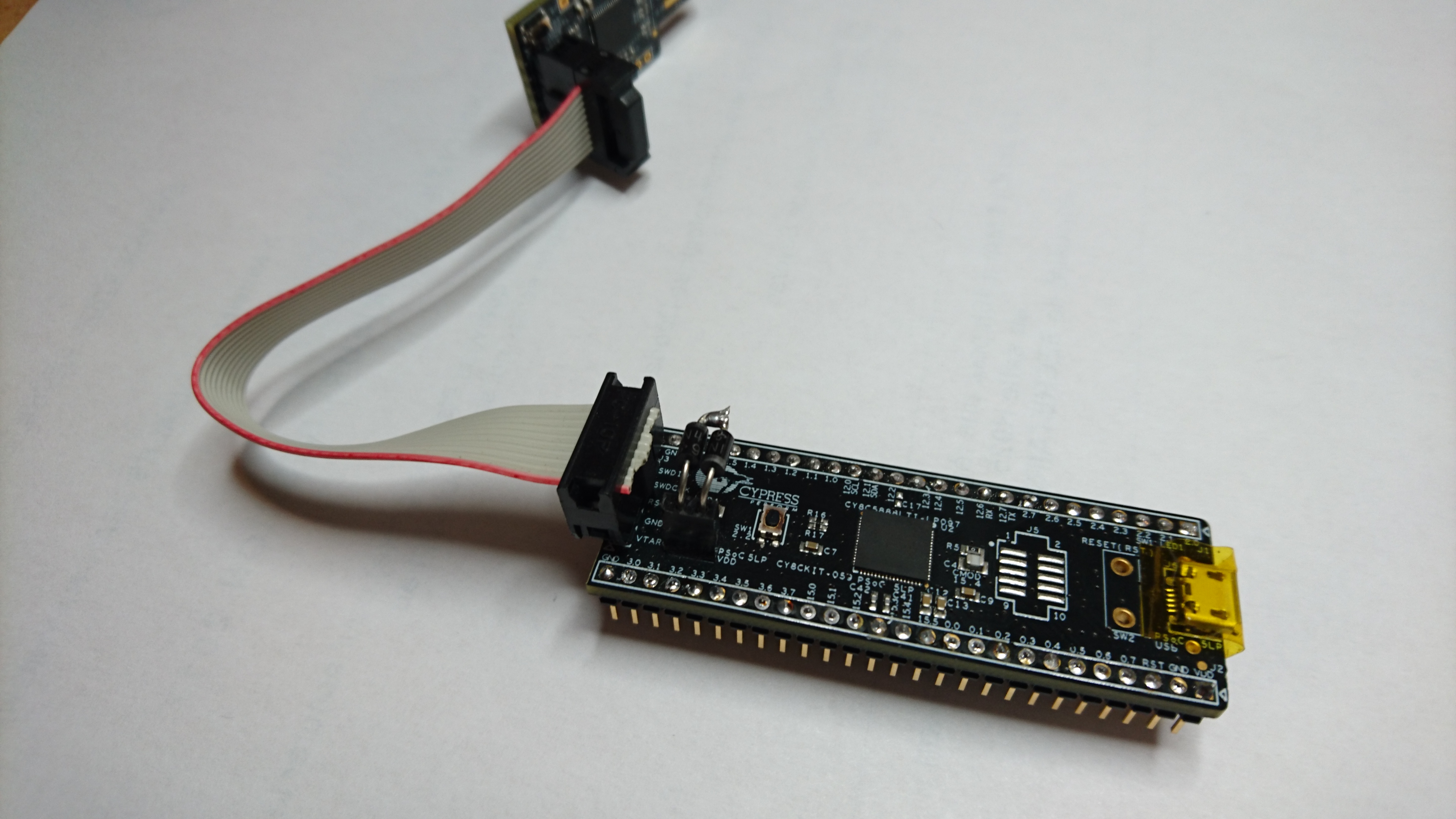
User Guide says:
4.2.3 Power Supply System
The power supply system on this board is dependent on the source of the power. For most applications,
you can use the 5 V supply from the USB connection to power the system. You can also connect
an external power supply to the board for low-voltage applications. The kit supports the
following connections:
■ 5 V from the PCB USB
■ 1.8-5 V from a regulated supply connected to VDD
It is important to understand that this prototyping kit does not have any onboard ESD protection circuitry.
Therefore, the power source for the PSoC 5LP Prototyping Kit must be of a high quality to
ensure that the board is protected from any over-current conditions and swapped-power connections.
Bob
- Mark as New
- Bookmark
- Subscribe
- Mute
- Subscribe to RSS Feed
- Permalink
- Report Inappropriate Content
There is no onboard LDO / regulator. So it runs with whatever you power it.
One caveat: VBus on the KitProg is connected, with diode D1, to Vtarget (which is the power on the target board). That means if you want to power the target board with 3.3V, you need to remove that diode, otherwise KitProg will feed your power supply backwards with 5V.
(There is nothing mentioned in the user guide whether Vtarget needs to be connected between the two boards for programming to work - it might be that KitProg needs to know the target power supply voltage)
- Mark as New
- Bookmark
- Subscribe
- Mute
- Subscribe to RSS Feed
- Permalink
- Report Inappropriate Content
Thanks for all the information and pointers everyone...
However, I was interested in using it with a stand alone USB wart and some 3V peripherals.. so Plan B..
I'll have to save it for the next project 🙂
- Mark as New
- Bookmark
- Subscribe
- Mute
- Subscribe to RSS Feed
- Permalink
- Report Inappropriate Content
Assume you know about:
We cannot match the price but on the other hand we have them available for immediate shipment.
- Mark as New
- Bookmark
- Subscribe
- Mute
- Subscribe to RSS Feed
- Permalink
- Report Inappropriate Content
Consider making up a comparison table for decision makers.
Regartds, Dana.
- Mark as New
- Bookmark
- Subscribe
- Mute
- Subscribe to RSS Feed
- Permalink
- Report Inappropriate Content
Has it got debugging capabilities over USB? An UART-USB bridge? Does the board need a Bootloader to get programmed over USB? I'm very interested!
Bob
- Mark as New
- Bookmark
- Subscribe
- Mute
- Subscribe to RSS Feed
- Permalink
- Report Inappropriate Content
Bob, here are some links to answer your questions -
http://www.screencast.com/t/tcuMUDxn
Regards, Dana.
- Mark as New
- Bookmark
- Subscribe
- Mute
- Subscribe to RSS Feed
- Permalink
- Report Inappropriate Content
About Powerfulboard - www.powerfulboard.com
A schematic is available for download from the website.
Yes it has debugging capabilites over the USB connection. There is an FX2 chip on the board to make this happen.
I will attempt a comparison later. We have been shipping these boards for several years.
- Mark as New
- Bookmark
- Subscribe
- Mute
- Subscribe to RSS Feed
- Permalink
- Report Inappropriate Content
As requested I have prepared a comparison of the CY8CKIT-059 with the Powerfulboard equivalent. We also offer a PSoC3 based board.. I will add other items to the comparison list if someone suggests them here.
See:
http://www.powerfulboard.com/CY8CKIT-059
Hope this helps.
Bob M (not Marlow)

- Mark as New
- Bookmark
- Subscribe
- Mute
- Subscribe to RSS Feed
- Permalink
- Report Inappropriate Content
Hi . For an easy choice of supplies, remove R20, add a female SIL connector on J4 (see picture added)
To power a 3.3V application from the USB, insert 2 serial wired 1N4001 diodes in J4
To work with 5V application, set a wire in J4
To work with external supply, nothing in J4
I have worked for hours with a 3.3V touch-screen, the unaccurate 3.3V supply don't bother
Bye