

- Mark as New
- Bookmark
- Subscribe
- Mute
- Subscribe to RSS Feed
- Permalink
- Report Inappropriate Content
Hi all
Please help me how to use 2x analog filter component - visible only in advanced analog view mode. This is secret analog component ?
Very thanks any info Kamil
- Labels:
-
PSoC 5LP
- Mark as New
- Bookmark
- Subscribe
- Mute
- Subscribe to RSS Feed
- Permalink
- Report Inappropriate Content
There are two LPF Blocks available in PSoC 3/5. Each LPF can be tuned by changing the values of Resistor (R) and Capacitor (C). The Resistor value can be selected as 208K ohms or 1.04 M ohms. The Capacitor value can be selected as 5pF or 10pF. Hence four cut-off frequencies are supported by the LPF, that is, 15KHz, 30KHz, 76KHz and 153KHz.
Refer to the figure below which shows the Routing of the analog LPF.
The inputs are selectable in a 2:1 mux for each LPF. On the left side, the LPF inputs are AMUXBUSL and AGL0. On the right side, the inputs are AMUXBUSR and AGR0. The outputs are connected through switches to abusL0 and abusR0, respectively.
- Mark as New
- Bookmark
- Subscribe
- Mute
- Subscribe to RSS Feed
- Permalink
- Report Inappropriate Content
Hi JLS1,
Please refer to the Technical reference Manual (TRM) for more details on this block. The TRM can be found at http://www.cypress.com/?id=2232&rtID=117.
The LPF control registers are LPF0_CR0 and LPF1_CR0. The Control register is as shown below:

When csel = 0, C is 5pF
csel = 1, C is 10pF.
When rsel = 0, R is 208k ohm
rsel = 1, R is 1.04M ohm
When swout = 0, LPF output is not connected
swout = 1, LPF output is connected to Analog local bus 0.
When swin = 00, inputs are not connected.
swin = 01, Analog Global 0 is connected (AGL0 o/ AGR0)
swin = 10, Analog Muxbus is connected (AMUXBUSL / AMUXBUSR)
swin = 11, Both Analog Global and Analog Mux are connected.
- Mark as New
- Bookmark
- Subscribe
- Mute
- Subscribe to RSS Feed
- Permalink
- Report Inappropriate Content
These filters have only 4 cut-off frequencies. Since it acts as a simple R-C Low pass filter, the impedance matching has to be taken care of.
If you are intending to use this filter, then you'll have to buffer its input / output via an opamp or PGA in voltage follower mode. Else the signal will be attenuated.
- Mark as New
- Bookmark
- Subscribe
- Mute
- Subscribe to RSS Feed
- Permalink
- Report Inappropriate Content
Hi dasg
Very thanks info about LP filter.
Please is possible make simple working module ? This is very hard for me im dont understand how to use registers.
Many many thanks
Kamil
- Mark as New
- Bookmark
- Subscribe
- Mute
- Subscribe to RSS Feed
- Permalink
- Report Inappropriate Content
Hi JLS1,
As you are not comfortable using registers, it will be easier to use the component to configure and use the LPF.
The schematic will look as shown below:

The LPF's output is buffered via opamp and put out on an analog pin.
Please be aware that this LPF component is just a trial component and is not fully tested. You have choice of four frequencies - 15kHz, 30kHz, 76kHz and 153kHz.
The output impedance of the LPF is high, hence the output should be buffered before bringing it out on a pin.

- Mark as New
- Bookmark
- Subscribe
- Mute
- Subscribe to RSS Feed
- Permalink
- Report Inappropriate Content
- Mark as New
- Bookmark
- Subscribe
- Mute
- Subscribe to RSS Feed
- Permalink
- Report Inappropriate Content
Hi dasg
Many thanks this is very usefull module for me.
Kamil
- Mark as New
- Bookmark
- Subscribe
- Mute
- Subscribe to RSS Feed
- Permalink
- Report Inappropriate Content
You're welcome Kamil.
All the Best!
- Mark as New
- Bookmark
- Subscribe
- Mute
- Subscribe to RSS Feed
- Permalink
- Report Inappropriate Content
Hola.
Estoy haciendo un filtro pasabandas de 4 orden con un Psoc de la familia 1.
No entiendo bien los parámetros de frecuencia central y ancho de banda, tenía mis parámetros de la siguiente manera:
La señal que quiero filtrar está entre 20 Hz y 500 Hz; si sigo la lógica de filtros la frecuencia central está dada por la raíz del producto de éstas dos frecuencias, es decir FC = SQRT(500*200) = 100 Hz; ahora bien, el ancho de banda es la diferencia de las dos frecuencias, es decir BW = 500 - 20 = 480 Hz
Con esta lógica no funciona mi filtro.
Agradecería que me pudieran aclarar o dar un tutorial de cómo calcular bien el ancho de banda y la frecuencia central para ese pasabandas.
Gracias
- Mark as New
- Bookmark
- Subscribe
- Mute
- Subscribe to RSS Feed
- Permalink
- Report Inappropriate Content
- Mark as New
- Bookmark
- Subscribe
- Mute
- Subscribe to RSS Feed
- Permalink
- Report Inappropriate Content
- Mark as New
- Bookmark
- Subscribe
- Mute
- Subscribe to RSS Feed
- Permalink
- Report Inappropriate Content
- Mark as New
- Bookmark
- Subscribe
- Mute
- Subscribe to RSS Feed
- Permalink
- Report Inappropriate Content
- Mark as New
- Bookmark
- Subscribe
- Mute
- Subscribe to RSS Feed
- Permalink
- Report Inappropriate Content
Would this moved back to PSoC1sub forum?
- Mark as New
- Bookmark
- Subscribe
- Mute
- Subscribe to RSS Feed
- Permalink
- Report Inappropriate Content
Sorry, I mean the new one, not the original one.
- Mark as New
- Bookmark
- Subscribe
- Mute
- Subscribe to RSS Feed
- Permalink
- Report Inappropriate Content
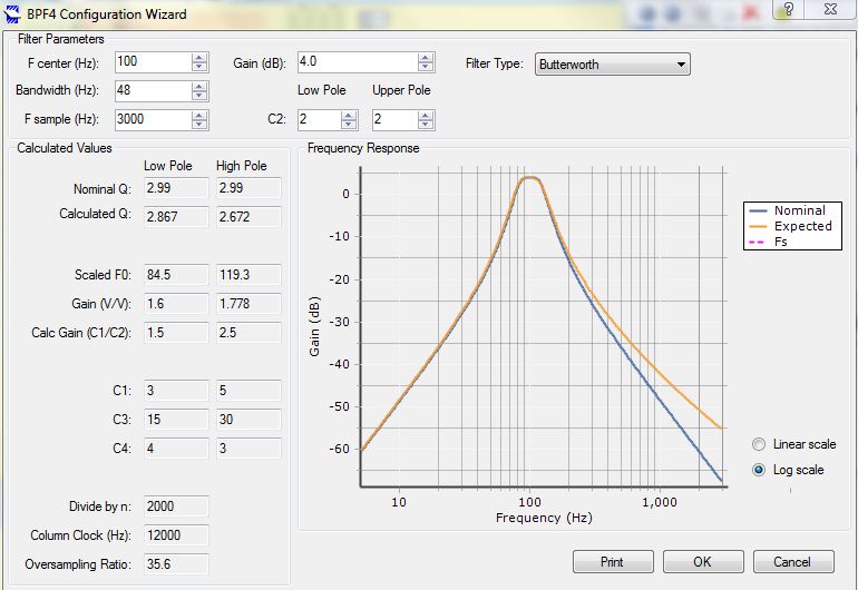
You want to use geometric mean or arithmetic mean ? 100 Hz vs 260 Hz ?
www.sengpielaudio.com/calculator-geommean.htm
Equiripple, linear phase, maximally flat.....?
Out of band rejection ?
2'ond order, 4'th order ? (Above will tell us this)
Regards, Dana.
- Mark as New
- Bookmark
- Subscribe
- Mute
- Subscribe to RSS Feed
- Permalink
- Report Inappropriate Content
- Mark as New
- Bookmark
- Subscribe
- Mute
- Subscribe to RSS Feed
- Permalink
- Report Inappropriate Content
An excellent tool where you can establish filter order needed to implement
a set of design goals and evaluate filter -
Regards, Dana.
- Mark as New
- Bookmark
- Subscribe
- Mute
- Subscribe to RSS Feed
- Permalink
- Report Inappropriate Content
Bob, using Firefox, I clear all history, and after 1 or 2 trys the large window is restored.
Restart browser after each attempt.
Regards, Dana.
- Mark as New
- Bookmark
- Subscribe
- Mute
- Subscribe to RSS Feed
- Permalink
- Report Inappropriate Content
The LPF component is not available in PSoC Creator 3.0. I can open the sample project above and it updates the components OK, but I can't copy/paste it to a current project. Am I missing something? I see the grayed-out blocks in the Analog section of .cydwr but I have no way to use them.
- Mark as New
- Bookmark
- Subscribe
- Mute
- Subscribe to RSS Feed
- Permalink
- Report Inappropriate Content
Does not appear to be part of the standard library, did you import
the component from the project in this thread ? Don't forget to update
the dependencies setting for this project.
Note the accuracy/tolerance of the cutoff freq for this componet very poor. The absolute R tolerance
is poor so you will get a big variation. You can get an idea of the tolerance by looking at the TIA feedback
R tolerance in datasheet. 60%
Regards, Dana.
- Mark as New
- Bookmark
- Subscribe
- Mute
- Subscribe to RSS Feed
- Permalink
- Report Inappropriate Content
- Mark as New
- Bookmark
- Subscribe
- Mute
- Subscribe to RSS Feed
- Permalink
- Report Inappropriate Content
Hi Gautam Das,
Can you tell me how you created this Component (Low Pass Filter - LPF) ? I have some problems with creating new components 😞
Thanks.
- Mark as New
- Bookmark
- Subscribe
- Mute
- Subscribe to RSS Feed
- Permalink
- Report Inappropriate Content
You are aware PSOC 3 / 5LP has a digital filter in it ?
Also you can use an OpAmp as a LPF by running at at low power thereby
reducing its GBW, or use it in a general Salllen-Key configuration.
Maybe describe what you are filtering and what performance you want out
of the filter would help with recomendations.
Regards, Dana.
- Mark as New
- Bookmark
- Subscribe
- Mute
- Subscribe to RSS Feed
- Permalink
- Report Inappropriate Content
Hi danaaknight, thanks for answer.
I am trying to make a low pass filter with cut frequency at 212Hz. I used an circuit that works with this frequency but it has external components and i need a circuit without external components.
I am sending attachment with image of my circuit.
- Mark as New
- Bookmark
- Subscribe
- Mute
- Subscribe to RSS Feed
- Permalink
- Report Inappropriate Content
The LPF component has fixed cutoffs, none of which come close
to the 212 Hz you need. Thats because of the available onchip Rs and
Cs available.
If you are using PSOC 3 or 5LP then use the DFB, otherwise you will have
to use external components. Or use code + A/D to do your own filter algorithim
if using PSOC 4. Note PSOC 4 has a single cycle digital 32 bit multiplier in
it that facilitates digital filtering.
There is this approach, but if using PSOC 4 would have to be 4M family.
http://www.cypress.com/?app=forum&id=2492&rID=76870
And this -
http://www.cypress.com/?rID=2813 AN2099
Regards, Dana.
- Mark as New
- Bookmark
- Subscribe
- Mute
- Subscribe to RSS Feed
- Permalink
- Report Inappropriate Content
Thank you Dana for helping me. I will study more about this components that you sent to me now.
Regards, Miguel.
- Mark as New
- Bookmark
- Subscribe
- Mute
- Subscribe to RSS Feed
- Permalink
- Report Inappropriate Content
For PSOC 4 use the MULS instruction, inline ASM, to perform the
single cycle multiply -
Regards, Dana.
- Mark as New
- Bookmark
- Subscribe
- Mute
- Subscribe to RSS Feed
- Permalink
- Report Inappropriate Content
Hello Everybody!
Seems as Cypress has taken the analog LPF from the available components. Even the import doesn't work anymore. What happened?
Thanks and bye!
Andreas
- Mark as New
- Bookmark
- Subscribe
- Mute
- Subscribe to RSS Feed
- Permalink
- Report Inappropriate Content