

- Mark as New
- Bookmark
- Subscribe
- Mute
- Subscribe to RSS Feed
- Permalink
- Report Inappropriate Content
Hello
I'm looking for the easiest way of using PSoC5 to make a:
* 3 identical squared signals, shifted 120 degrees (It could change to be a SPWM sinus signal, but for now, a PWM could be enough)
* About 5 KHz, 20% tunnable by program, (depending on an audible feedbak captured with a microphone)
* Able to read 3 I2c, 2 ADC with low resolution, the audio, and act as programmed
* Handling an LCD Display
* With an interruptions clock to know each round of program if tasks, as the LCD, are ready, instead of being waiting for their answer to can continue attending the generation of signals
My real problem has been to know how to generate this 3 signals, so If solving the generation of them, the rest can go further easily.
Luis
Solved! Go to Solution.
- Labels:
-
PSOC5 LP MCU

- Mark as New
- Bookmark
- Subscribe
- Mute
- Subscribe to RSS Feed
- Permalink
- Report Inappropriate Content
Luis,
I've attached a very simple project. I believe it solves your 3 phase (120 degrees apart) PWM signals at about 5KHz.
Each of the 3 phases of PWM are set to 50% DC which can be changed in the SW.
Here is a scope pic of the 3 phases.

"Engineering is an Art. The Art of Compromise."
- Mark as New
- Bookmark
- Subscribe
- Mute
- Subscribe to RSS Feed
- Permalink
- Report Inappropriate Content
Luis,
I've attached a very simple project. I believe it solves your 3 phase (120 degrees apart) PWM signals at about 5KHz.
Each of the 3 phases of PWM are set to 50% DC which can be changed in the SW.
Here is a scope pic of the 3 phases.
"Engineering is an Art. The Art of Compromise."
- Mark as New
- Bookmark
- Subscribe
- Mute
- Subscribe to RSS Feed
- Permalink
- Report Inappropriate Content
I really appreciate your answer. I'll study this and try to implement what I need.
Thank you a lot,
Luis
- Mark as New
- Bookmark
- Subscribe
- Mute
- Subscribe to RSS Feed
- Permalink
- Report Inappropriate Content
Luis,
If your requirements are that each phase output is 50%DC, I have more efficient project.
It uses extremely little PSoC resources and eliminates the need for the PWM components.
It only uses a LUT (Look Up Table) to generate the 6 transition states needed.
Because the source clock for this LUT is 30 KHz for 5 KHz outputs, you can adjust the phase frequency +/- 0.04% for each divider value count.


As you can see, the TopDesign schematic is VERY SIMPLE!

This design is attached to this post.
The great thing about this project (and the PSoC in general) is that this phase generation requires no SW to keep it going. You only need SW to make changes to the output only if you need.
"Engineering is an Art. The Art of Compromise."
- Mark as New
- Bookmark
- Subscribe
- Mute
- Subscribe to RSS Feed
- Permalink
- Report Inappropriate Content
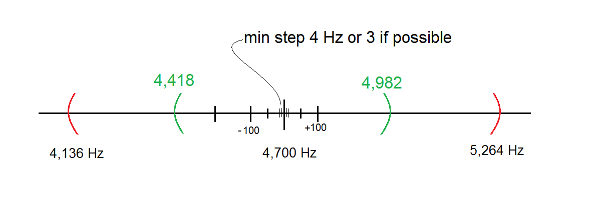
Excuse me for the delay. I'm now back with this problem. As I stated first, I need to move frequency about +- 12% from a frequency, that is a little lower than 5 KHz, in order to sustain some resonance on the system. i have seen what you sent, I understand that the clock was defined as the 8 bit period (256) multiplied by 5,000 Hertz, so you get a clock of 1.28 MHz. but as I need to move smoothly the frequency from the program (see the image), I see at first sight two posibilities:
1. To change the frequency on the clock with Clock_SetDividerValue(uint16 clkDivider) or
2. To change Period of the first PWM
The problem is that I don't know which values are elegible in case 1. and that the steps that would be available in case 2. are very wide (18.35 Hertz per step), and, if the range is about 564 Hertz for each side, with 30 steps I'll never can sustain resonance (I would correct from a derivative control factor, but if it doesn't work, it would become a PID algorithm). I think that the minimal step should be about 4 or 3 Hz. At the beginning, the program will scan the range until it finds the resonance frequency. The input for the program will be a sound, so when amplitude reach a peak, the program has to avoid loosing resonance moving frequency as needed. The resonance freq. could vary a little with rise of temp, the system has to make the changes needed, if amplitude begin to decrease, it has to oscilate slowly to verify on which direction it reaches the peak again (zero slope). I think that the green range, of about 500 Hz will be enough, but I'll know it until the experiment be phisically implemented.
Another thing that I want you to help me is the next: I have to sustanin resonance, but I want to read and display several sensors (a microphone, temp, presure, amp, volt, etc). How can I do all that? That is, I think I have to avoid to wait for response, it be a sensor, the display or whatever, so I think I would have to have a clock and each component would check if the delay time is reached for it, each round of the program, so for instance, it could send another data to display or it could read an ADC register if a flag is now on on each one. This way I don't interrupt the frequency generator. (supposing that it become stopped while a delay instruction is working) So, if You could help me to make clear this item I'd thank you a lot.
I have not reviewed the other example you gently sent me, but from a surface sight, I think that LUT can't comply with the requirement of min step here stated, but you can correct me if I'm wrong.
I wonder if, as it is marked as solved (I don't understand what for is that costume of setting as solved this), this question will be seen and attended. I hope it be...
Thank you again
Luis
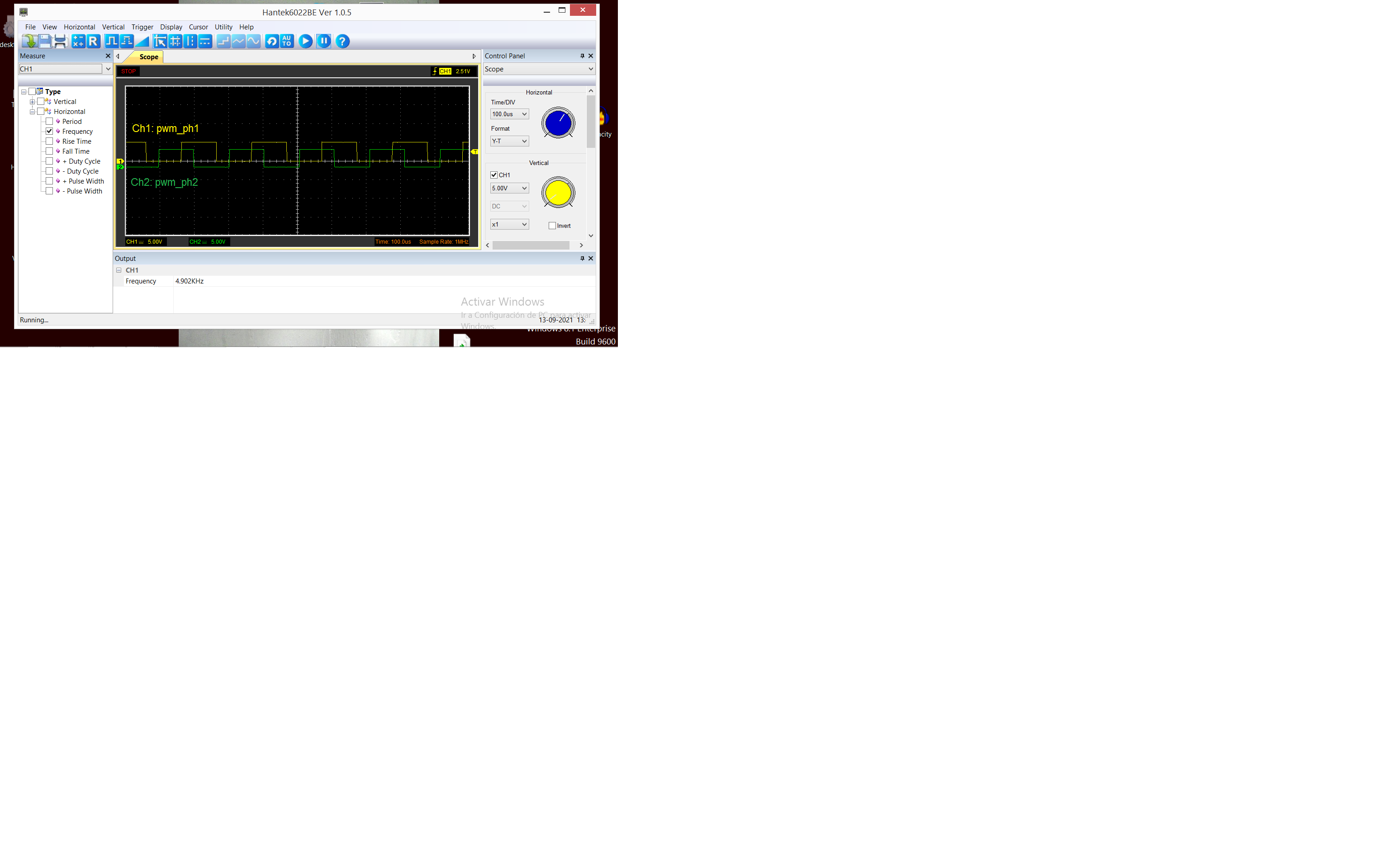
I have checked the signal of the example in my psoc 5 and an image of it is attached.
- Mark as New
- Bookmark
- Subscribe
- Mute
- Subscribe to RSS Feed
- Permalink
- Report Inappropriate Content
Hi,
Although Len-san has already posted an answer, as I spent a couple of hours on this, let me post mine, too 😉
Meantime I realized that my waveform is different from the one of Len-sans, may be I need to study more...
My strategy was using 3 PWMs with the same period and let them generate pulse in 120 degree difference(s).
When my program started, on the serial terminal we have some controls.
Entering "status" shows the status of PWMs
Since period is set to 239 the real period is 240 (0 - 239) so each pulse should have 1/3 = 80,
so
PWM1 : 160 - 239
PWM2: 80 - 159
PWM3: 0 -79
When I enter "period 299" which set the real period to 300 (0 - 299),
the configuration was shown in the second block.

When the period was 239 (real period = 240)

when the period was 299 (real period = 300)

I tried this with CY8CKIT-059
schematic

pins

And each for the end of the period, isr_1 is triggered.
CY_ISR(pwm_3phase_isr)
{
    pwm_3phase_flag = 1 ;
    PWM_3_ReadStatusRegister() ;
    LED_Write( ~LED_Read() ) ; /* toggle LED */
}
Although I assumed that each signal has 1/3 width of the period,
you can tweak it by modifying pwm_3phase_set_period() in pwm_3phase.c
void pwm_3phase_set_period(uint16_t period)
{
    uint16_t real_period, period3 ;
    uint16_t tmp ;
    uint16_t delta1 = 0 ;
    uint16_t delta2 = 0 ;

    real_period = period + 1 ;
    period3 = (real_period) / 3 ;
    PWM_1_WritePeriod(period) ;
    PWM_2_WritePeriod(period) ;
    PWM_3_WritePeriod(period) ;

    switch(real_period - (period3 * 3)) {
    case 0: break ;
    case 1: delta1 = 1 ; break ;
    case 2: delta1 = 1 ; delta2 = 1 ; break ;
    }

    tmp = period ;
    PWM_1_WriteCompare2(tmp) ;
    tmp = real_period - (period3 + delta1) ;
    PWM_1_WriteCompare1(tmp) ;

    tmp = tmp - 1 ;
    PWM_2_WriteCompare2(tmp) ;
    tmp = real_period - (2 * period3 + delta1 + delta2) ;
    PWM_2_WriteCompare1(tmp) ;

    tmp = tmp - 1 ;
    PWM_3_WriteCompare2(tmp) ;
    PWM_3_WriteCompare1(0) ;

    pwm_3phase_reset() ;
    pwm_3phase_enable() ;
}
moto
P.S. (added)
lol, I mistook that period was 50kHz, for 5kHz, period must be 2399 ... orz
- Mark as New
- Bookmark
- Subscribe
- Mute
- Subscribe to RSS Feed
- Permalink
- Report Inappropriate Content
Thank you very much. I'll study it and compare with the previus proposal.
Sincerly
Luis
- Mark as New
- Bookmark
- Subscribe
- Mute
- Subscribe to RSS Feed
- Permalink
- Report Inappropriate Content


- Mark as New
- Bookmark
- Subscribe
- Mute
- Subscribe to RSS Feed
- Permalink
- Report Inappropriate Content
I'm testing what I received, and I have two jobs, so, it would be wonderful don't be pushed to say that this is a SOLVED thing until I know it, and that is to come yet. I have some questions, but I preffer first to see with the CY8Kit working with that proposed. In fact, I have to solder some wires, and I was seeing that this circuit has not any hole for fixing it, all holes are for signals, so I could make a printed circuit who has the female connector where a male one, connected to the CY8kit, be inserted. Or letting it flying just pending of some wires... etc. So, some time from now and I'll can answer if it is solved. Don't force things.
- Mark as New
- Bookmark
- Subscribe
- Mute
- Subscribe to RSS Feed
- Permalink
- Report Inappropriate Content
I don't know why this conversation has been tagged as solved, if we are just begining to deal with this issue. Is it possible to untag this conversation as solved???
- Mark as New
- Bookmark
- Subscribe
- Mute
- Subscribe to RSS Feed
- Permalink
- Report Inappropriate Content
Luis,
What other questions do you have on this issue?
"Engineering is an Art. The Art of Compromise."
- Mark as New
- Bookmark
- Subscribe
- Mute
- Subscribe to RSS Feed
- Permalink
- Report Inappropriate Content
Many questions.
First. I need to tune the signal, but the feedback will be the amplitude of a sound coming trhough a microphone. I don't know how to move frequency with your components and code. I saw that it is possible with dds24 to tune frequencies in (https://community.cypress.com/t5/Code-Examples/DDS24-24-bit-DDS-arbitrary-frequency-generator-compon...),
although it is a single phase signal, and is working in a different range. What I need is to read an ADC conncected to a microphone, to calculate slope, to find zero of it, and then, to sustain, modifiyng the frec., the resonance obtained previusly. I don't know if DDS24 be optimal, if there is another better component to do what I need, but the previous example, I don't see how to make a tunning between the frequencies 4,200 and 5,200 Hertz, smoothly as stated in (https://community.cypress.com/t5/PSoC-5-3-1-MCU/Things-are-not-solved-until-they-are-solved-3-phase-...) I apologize if the begining of the previous text was not very polite, but I'm still needing your help, so I'll be very thankfull if you help me to know how to solve this 3 phase, tunnable, about 5 KHz, with this kind of feedback through a microphone, system.
Have a good day
Luis
- Mark as New
- Bookmark
- Subscribe
- Mute
- Subscribe to RSS Feed
- Permalink
- Report Inappropriate Content
Luis,
It appears you are looking for +/- 3 Hz resolution in the clock control.
The project I uploaded inputs the 3 phase clock (@ 30KHz) derived from the MASTER_CLK of 78 MHz. Each count of the Divider to this clock resource will provide +/- 11.53 Hz resolution. Changing the clock is easy. Use the clk_3ph_SetDividerValue() API call.
However, either way it is at least 4 times the resolution you are seeking.
I'm not familiar with the DDS24 but it may provide the resolution you desire. Substitute the DDS24 clock as the input to LUT_1. Control of the DDS24 output frequency should be accessible from API calls.
Try it. At worst, it might not be enough but it will be a good learning experience.
"Engineering is an Art. The Art of Compromise."
- Mark as New
- Bookmark
- Subscribe
- Mute
- Subscribe to RSS Feed
- Permalink
- Report Inappropriate Content
Thank you for your post
What do you think about VCO (https://community.cypress.com/t5/Knowledge-Base-Articles/Voltage-Controlled-Oscillator/ta-p/248246)? Would it be modifiable via an API call?
I'd like to know from the experts as you what components are the optimal to do this, then to focus on many details I have to deal with, but having the certainity of being on the right way, not just going with trying - error components. So I would hope you kindly help me to define those components who fits the needs stated. Yes, I'll be learning, but I'd thank you to help me shorten the way.
Thank you for your time
Luis
- Mark as New
- Bookmark
- Subscribe
- Mute
- Subscribe to RSS Feed
- Permalink
- Report Inappropriate Content
Luis,
The VCO method may work. However it will be a challenge to determine the actual output frequency since the Vin and C value can have a bit of variance. Besides, changing a divider value is much easier and more accurate given the IMO driving the MASTER_CLK is at +/-0.25%.
Have you tried the DDS24 component. It might give you the +/-3 Hz resolution you are looking for.
"Engineering is an Art. The Art of Compromise."