


- Mark as New
- Bookmark
- Subscribe
- Mute
- Subscribe to RSS Feed
- Permalink
- Report Inappropriate Content
Hello,
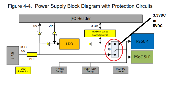
Looking at J9 at SCHEM1 seems to represent J9 on SCHEM2 which seems to suggest that depending on the jumper of J9, the PSoC 4 and PSoC 5LP chips will be powered by either the USB's 5VDC or the 3.3VDC via the LDO power supply system. The jumper chosen on J9 will represent the VDD volatge throughout the parts connections. (Please confirm if I am assuming this correctly!)
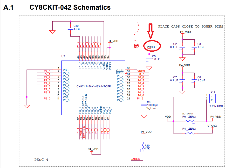
In SCHEM3, we have VCCD??? Where does this come from???
Thank you
All help appreciated
r
Solved! Go to Solution.
- Labels:
-
PSoC 4 MCU
- Mark as New
- Bookmark
- Subscribe
- Mute
- Subscribe to RSS Feed
- Permalink
- Report Inappropriate Content
Hello.
Your observations are correct regarding J9 selecting 3.3V or 5V for all parts connections.
Vccd is an internal PSoC voltage regulator at 1.8Volts. It only needs a capacitor connected to this pin (as shown in SCHEM3). On KIT-042, you do not need to do anything with Vccd.
Read PSoC 4 family datasheet "Power" chapter and find more information. In the future, if you make your own pcb design, follow the schematic from KIT-042 for power supply connections. It's extremely important to use Vccd properly. In general, it only needs a capacitor. It doesn't connect to ANYTHING else. If the PSoC is being powered from 1.8V (instead of 3.3v or 5V), there are options shown in the "Power" chapter.
But for now, enjoy KIT-042. Lots of things to do with it.
Good luck with your project.