


- Mark as New
- Bookmark
- Subscribe
- Mute
- Subscribe to RSS Feed
- Permalink
- Report Inappropriate Content
Hi,
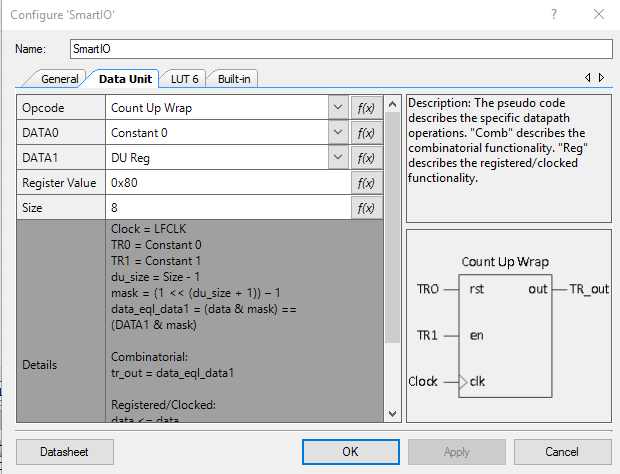
The DU wasn't available on PSoC Creator 4.0, the new version of Creator (4.1) have the DU available on the SmartIO customizer. There's not appnotes available of using the DU, so i did one dummy project.
The DU opcode is Count up and Wrap, starts from the number on DATA0 which in the project is 0, counts up by 1 until it reaches the number in DATA1 (0x80 in the project), when the count reaches 0x80 the DU output is high by one clock cycle, in this project the SmartIO clock is provided by the PSoC LPCLK (40 kHz if i remember correctly).
The DU is always enabled (the Trigger1 signal is connected to logic 1), so the DU generates a periodic signal, in the project i use the LUT6 to invert the signal and the LUT output connects to the onboard LED.
Two of the LUT6 inputs (input 1 and 2) are connected to gpio5, this pin is connected to Vcc to give the LUT inputs a logic high value, i whish to connect the LUT inputs directly to a logic 1 but it seems not possible, one gpio wasted there.
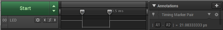
The result is a signal which is 0x79 times the LPCLK period in logic high, and 0x01 times the LPCLK period in logic low state.
So, attached are the workspace itself (project named CountUpWrap, there are more projects but one is a blinky to prove my CY8CKIT-41-40XX kit is working properly and the other project is not finished) and some pictures of the CountUpWrap project and a couple of logic analyzer captures of the signal that drives the LED (LUT output).
Hope it's useful to all.
Carlos
- Mark as New
- Bookmark
- Subscribe
- Mute
- Subscribe to RSS Feed
- Permalink
- Report Inappropriate Content
Thanks for your contribution 