


- Mark as New
- Bookmark
- Subscribe
- Mute
- Subscribe to RSS Feed
- Permalink
- Report Inappropriate Content
Hi,
I come from the Alt*ra world (FPGAs with soft Nios processor), so this is my first look at using something different..
Aside from a few quirks, like the 'Find All Active References' not finding all the active references, I think the PSoc Creator is a very good tool... the design flow is intuitive and user-friendly. I still haven't played with it enough to know if I I'll be able to implement custom logic in Verilog, but I like what I see so far.
My biggest concern at the moment however, is (2) issues with the Arm debugging for the Motor Kit. ( I'm using the Pioneer Kit with the Sensorless BLDC example, C:\Program Files (x86)\Cypress\CY8CKIT-037 Motor Control EVK\1.0\Firmware\Example Projects\Sensorless BLDC Motor Control).
#1 Once 'CyGlobalIntEnable' is executed. I can no longer single step in/over any code. Instead stepping always puts me in the 'CY_ISR(PWM_Drive_ISR)' . To get around this, I use breakpoint with 'run' resume only (no stepping). Other times, the program will execute (Led D9 will blink), but no breakpoint (including the one in CY_ISR) ever hits.. instead when I pause it, the code is in 'CyDelayCycles'.
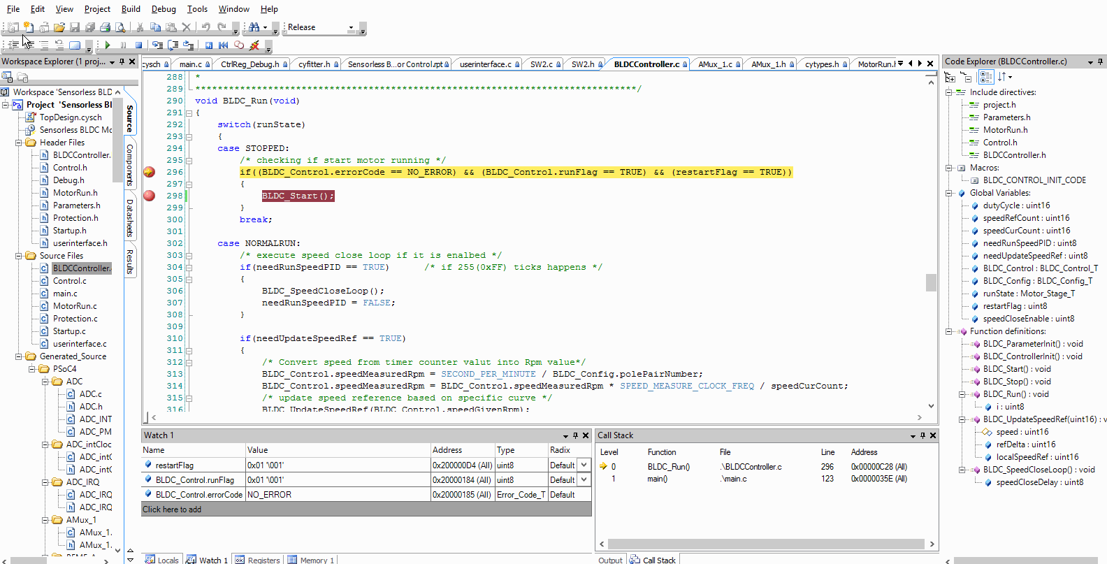
#2 The reason I'm debugging is because the motor fails to run, presumably because the state machine in the code never changes from STOPPED to NORMALRUN. What's strange however, is that the watch window shows all the correct variable values needed for it to execute BLDC_Start(), i.e. No Error, runFlag==TRUE, and restartFlag==TRUE. See attached animated gif.
<CODE>
if((BLDC_Control.errorCode == NO_ERROR) && (BLDC_Control.runFlag == TRUE) && (restartFlag == TRUE))
{
BLDC_Start();
}
</CODE>
Any suggestions what I could be doing wrong to cause this? I'm using the Creator 3.2 on the Pioneer Kit, running the example with no changes.
- Mark as New
- Bookmark
- Subscribe
- Mute
- Subscribe to RSS Feed
- Permalink
- Report Inappropriate Content
I ussually set optimization to 'None', this can be done on Project -> Build Settings -> ARM GCC -> Compiler -> Optimization
Maybe this can help you.
- Mark as New
- Bookmark
- Subscribe
- Mute
- Subscribe to RSS Feed
- Permalink
- Report Inappropriate Content
You may disable interrupts when debugging in single-step mode using the icon in Creator's menu bar. Re-enable interrupts when you verified what you were interested in.
From your code-snipped I cannot see what's going amiss, usually it is easier when you provide us with the complete project . To do so, use
Creator->File->Create Workspace Bundle (minimal)
and attach the resulting file.
Bob
- Mark as New
- Bookmark
- Subscribe
- Mute
- Subscribe to RSS Feed
- Permalink
- Report Inappropriate Content
... oh, yes, and when you remove the upper breakpoint you will see that the BLDC_Start() will be called.
Bob
- Mark as New
- Bookmark
- Subscribe
- Mute
- Subscribe to RSS Feed
- Permalink
- Report Inappropriate Content
I assume this is the project you are using ?
Regards, Dana.
- Mark as New
- Bookmark
- Subscribe
- Mute
- Subscribe to RSS Feed
- Permalink
- Report Inappropriate Content
@Dana : Yes, that's the kit I'm using, however I have my own motor & drivers that I wish to ultimately use with the psoc4.
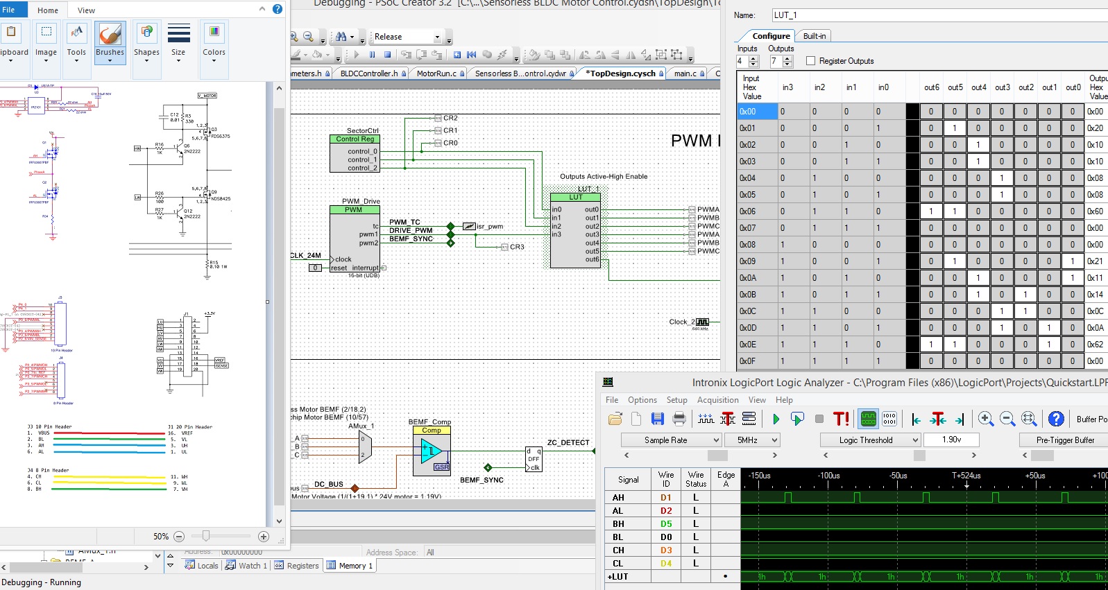
I'm familiar with 6-step trapezoidal commutation (3-inputs to the LUT) to determine the 6 different combinations that the outputs can be... but the example uses a 4 input LUT to drive the outputs, what does the extra PWM input do? Perhaps how this BLDC example works should be it's own thread, but I'm wondering this since the motor spins for a fraction of a second, then the power supply current limits (3A), and the debugger reports a zero crossing error.
Looking at the inputs to the LUT, I see it starts with 0<->8, then transitions between, 1<->9 forever. I find it odd that during the startup/open-loop portion, that the state machine doesn't cycle between 9-14 in order to generate sufficient back-emf.
- Mark as New
- Bookmark
- Subscribe
- Mute
- Subscribe to RSS Feed
- Permalink
- Report Inappropriate Content
The kit user guide discusses the algorithms and the use of PWM.
Regards, Dana.