

- Mark as New
- Bookmark
- Subscribe
- Mute
- Subscribe to RSS Feed
- Permalink
- Report Inappropriate Content
hi. i need your help.
i tested some our company's product with cypress fram.
i checked cypress fram's spec.
| FM24V02A-GTR spec | tested data | |||||
| min | max | unint | 測定値 | |||
| Fscl | - | 1 | MHz | 199.005 | kHz | |
| Thigh | 260 | - | ns | 2.42 | us | |
| Tlow | 500 | - | ns | 2.42 | us | |
| Tr | - | 120 | ns | 130 | ns | NG |
| Tf | 20(vdd/5.5v) | 120 | ns | 25 | ns | |
| Thd:sta | 260 | - | ns | 1.08 | us | |
| Tsu:sta | 260 | - | ns | |||
| Thd:dat | 0 | - | ns | 130 | ns | |
| Tsu:dat | 50 | - | ns | 1.93 | us | |
| Tdh:dat | 130 | ns | ||||
| Tsu:sto | 260 | - | ns | 1.38 | us | |
| Taa | - | 450 | ns | 520 | ns | NG |
| Tbuf | 500 | - | ns | 139.75 | us | |
| Tsp | 0 | 50 | ns | 0 | - | |
then, Tr and Taa is out of spec.
i think, it is ok . because Fscl is 200kHz.
are you guys also think it is ok?
Solved! Go to Solution.
- Labels:
-
ispn:38305:1:0
-
l1:4041:1:0
-
l2:4043:1:0
- Mark as New
- Bookmark
- Subscribe
- Mute
- Subscribe to RSS Feed
- Permalink
- Report Inappropriate Content
Hi Hana,
We looked into the table where you have made all the measurements with the scope. Tr spec as mentioned in the datasheet has a max limit of 120 ns while what you are measuring is 130 ns. Please note this is the rise time of the clock signal that you have to provide to the FRAM on the SCL pin. So, the datasheet clearly states that the rise time of this clock pulse should be max 120 ns while in your case it is 130 ns which means that the FRAM is operating outside the limits mentioned in the datasheet, which is one of the reason why Taa spec is not meeting its timing specs as in the datasheet. We will suggest you to provide a clock pulse from your controller which has a rising time lower than the 120ns spec and check for these results again. (You can check the schematics of your test board to see if you can change something there to improve the rise time.Lowering the resistance or capacitance/load on the SCL line will help you improve the spec)
As far as 200KHz is concerned you can operate at this frequency as there is no limit to the lower frequency in I2C.
Thanks and Regards,
Pradipta.
- Mark as New
- Bookmark
- Subscribe
- Mute
- Subscribe to RSS Feed
- Permalink
- Report Inappropriate Content
Hi
Can you elaborate more on your test procedure.
Can you also specify in which mode are you working. Is it the high speed mode ?
Can you share the scope shots also that you used to measure these values.
Thanks and Regards,
Pradipta.

- Mark as New
- Bookmark
- Subscribe
- Mute
- Subscribe to RSS Feed
- Permalink
- Report Inappropriate Content
HI
1. Original circuit(vdd 5v) -> add level change circuit, change the pull-up R and fram(vdd 3v)
After it, I just checked the ac characteristic using osc.
2. I think it was fast-mode.
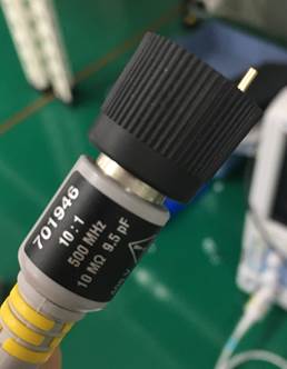
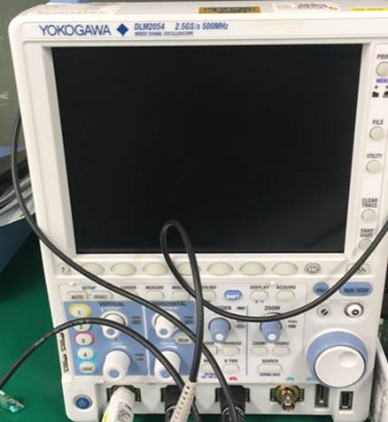
3. I tested it using yokogawa’s osc and probe.
Thanks,
hana.
FM24V02A-GTR
min
max
unint
UT55A
Fscl
-
1
MHz
199.005
kHz
Thigh
260
-
ns
2.42
us
Tlow
500
-
ns
2.42
us
Tr
-
120
ns
130
ns
Tf
20(vdd/5.5v)
120
ns
25
ns
Thd:sta
260
-
ns
1.08
us
Tsu:sta
260
-
ns
Thd:dat
0
-
ns
130
ns
Tsu:dat
50
-
ns
1.93
us
Tdh:dat
0
0
0
130
ns
Tsu:sto
260
-
ns
1.38
us
Taa
-
450
ns
520
ns
Tbuf
500
-
ns
139.75
us
Tsp
0
50
ns
[cid:image005.jpg@01D495EB.9AFA86F0]
- Mark as New
- Bookmark
- Subscribe
- Mute
- Subscribe to RSS Feed
- Permalink
- Report Inappropriate Content
Hi Hana,
We looked into the table where you have made all the measurements with the scope. Tr spec as mentioned in the datasheet has a max limit of 120 ns while what you are measuring is 130 ns. Please note this is the rise time of the clock signal that you have to provide to the FRAM on the SCL pin. So, the datasheet clearly states that the rise time of this clock pulse should be max 120 ns while in your case it is 130 ns which means that the FRAM is operating outside the limits mentioned in the datasheet, which is one of the reason why Taa spec is not meeting its timing specs as in the datasheet. We will suggest you to provide a clock pulse from your controller which has a rising time lower than the 120ns spec and check for these results again. (You can check the schematics of your test board to see if you can change something there to improve the rise time.Lowering the resistance or capacitance/load on the SCL line will help you improve the spec)
As far as 200KHz is concerned you can operate at this frequency as there is no limit to the lower frequency in I2C.
Thanks and Regards,
Pradipta.
- Mark as New
- Bookmark
- Subscribe
- Mute
- Subscribe to RSS Feed
- Permalink
- Report Inappropriate Content
HI
I have some question.
You suggested reduce R or C.
But if I use it the present condition(Tr :130, Taa: 530) is it make other trouble?
Also I think
the thing Tr is exceed the 120ns was occurred by probe’s capacitance(maybe 10pF?)
I'm not sure if it's right or wrong, …
So reaaly I want to know is
Is it ok that I use the present condition (Tr :130, Taa: 530)
- Mark as New
- Bookmark
- Subscribe
- Mute
- Subscribe to RSS Feed
- Permalink
- Report Inappropriate Content
Hi Kim,
The parts should be operated under datasheet specified conditions for optimal performance.
Under the present condition (Tr : 130, Taa : 530) you are already observing that because the rise time is not within specs you are getting a delay in read as well in form of Taa. Over a period of time it can cause harm to the part as well. We will suggest you to verify once that Tr does not exceeds the spec data and then continue. We can only guarantee optimal performance and functionality of our parts when the datasheet conditions are met.
Thanks and Regards,
Pradipta.