

- Mark as New
- Bookmark
- Subscribe
- Mute
- Subscribe to RSS Feed
- Permalink
- Report Inappropriate Content

- Mark as New
- Bookmark
- Subscribe
- Mute
- Subscribe to RSS Feed
- Permalink
- Report Inappropriate Content
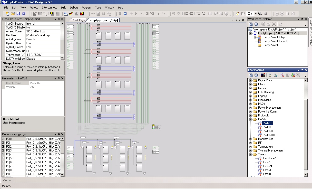
In the parameters window of PWM8 user module, set the "compare out" as Row0_Output0. Then, click on LUT on that row and click on the buffer which connects to GlobalOutEven4 (GOE 4). Then click on globalOutEven4 line and select the "pin" as P0[4].
Please see attached PDF file for example.
-Rajiv Badiger
- Mark as New
- Bookmark
- Subscribe
- Mute
- Subscribe to RSS Feed
- Permalink
- Report Inappropriate Content
and how to use timer for it ?
in MCS51 :
void delay_us (void) //100us delay on 12Mhz
{
TH0=0;
TL0=0;
TH0 = 0xFF;
TL0 = 0x37;
TR0 = 1;
while(!TF0);
TR0 = 0;
TF0 = 0;
return;
}
How can I create this on Cypress PSOC 1 ?
thanks
- Mark as New
- Bookmark
- Subscribe
- Mute
- Subscribe to RSS Feed
- Permalink
- Report Inappropriate Content
Easiest would be to use a PWM - Component and configure it accordingly. Have a look at the PWM's datasheet.
The way you showed in your example differs a bit from the way PSoCs work: Usually you do not need to access ports or pins directly, there are many pre-defined components: timers, PWM, counter, interfaces and you just have to configure them at design-time and start them with an API at run-time preferrably in c-language.
Bob
- Mark as New
- Bookmark
- Subscribe
- Mute
- Subscribe to RSS Feed
- Permalink
- Report Inappropriate Content
Some possibilities(besides the basic PWM module) -
http://www.cypress.com/?rID=2801
http://www.planetpsoc.com/component/content/article/71-prs-pwm.html
and the basic modules in Designer IDE (see lower right) -
Regards, Dana.
- Mark as New
- Bookmark
- Subscribe
- Mute
- Subscribe to RSS Feed
- Permalink
- Report Inappropriate Content
- Mark as New
- Bookmark
- Subscribe
- Mute
- Subscribe to RSS Feed
- Permalink
- Report Inappropriate Content
- Mark as New
- Bookmark
- Subscribe
- Mute
- Subscribe to RSS Feed
- Permalink
- Report Inappropriate Content
In the parameters window of PWM8 user module, set the "compare out" as Row0_Output0. Then, click on LUT on that row and click on the buffer which connects to GlobalOutEven4 (GOE 4). Then click on globalOutEven4 line and select the "pin" as P0[4].
Please see attached PDF file for example.
-Rajiv Badiger
- Mark as New
- Bookmark
- Subscribe
- Mute
- Subscribe to RSS Feed
- Permalink
- Report Inappropriate Content
The simplest way to see a PWM signal on your pin is using the PWM usermodule.
Place it in your project, configure the signal timing/duty using the usermodule parameters window (refer to the PWM datasheet for info on this; right click on the PWM block -> Datasheet)
Configure output as Rajiv mentioned; easier way is to do it graphically:
Hold Shift key and click on the "CompareOut" terminal, then click on the Pin of your choice.
Only code that you need to add in your main.c is PWM8_Start(); (PWM8 is the name of the usermodule, change accordingly)
Regards,
Arvind
- Mark as New
- Bookmark
- Subscribe
- Mute
- Subscribe to RSS Feed
- Permalink
- Report Inappropriate Content
Ok, I'll try and get back to you guys later,
thanks for helping
- Mark as New
- Bookmark
- Subscribe
- Mute
- Subscribe to RSS Feed
- Permalink
- Report Inappropriate Content
What's "LUT" ?
- Mark as New
- Bookmark
- Subscribe
- Mute
- Subscribe to RSS Feed
- Permalink
- Report Inappropriate Content
- Mark as New
- Bookmark
- Subscribe
- Mute
- Subscribe to RSS Feed
- Permalink
- Report Inappropriate Content
Click on LUT at end of ROW out, RO0(0) and this pops up
Regards, Dana.
- Mark as New
- Bookmark
- Subscribe
- Mute
- Subscribe to RSS Feed
- Permalink
- Report Inappropriate Content
Here are basic short videos to learn how to do HW routing and
a lot of other stuff for PSOC 1 -
http://www.cypress.com/?rID=40543
Regards, Dana.
- Mark as New
- Bookmark
- Subscribe
- Mute
- Subscribe to RSS Feed
- Permalink
- Report Inappropriate Content
- Mark as New
- Bookmark
- Subscribe
- Mute
- Subscribe to RSS Feed
- Permalink
- Report Inappropriate Content
From the data sheet (right click component and select data sheet )
TOUT = (PeriodValue+1)/FCLOCK
FOUT = FCLOCK/(PeriodValue+1)
The duty cycle equation also in datasheet.
And you should set a couple more properties. Note in datasheet are API f()
calls you can make to control PWM in software, like set period and dutycycle,
and to start the PWM.
Regards, Dana.
- Mark as New
- Bookmark
- Subscribe
- Mute
- Subscribe to RSS Feed
- Permalink
- Report Inappropriate Content
- Mark as New
- Bookmark
- Subscribe
- Mute
- Subscribe to RSS Feed
- Permalink
- Report Inappropriate Content
- Mark as New
- Bookmark
- Subscribe
- Mute
- Subscribe to RSS Feed
- Permalink
- Report Inappropriate Content
if the parameter of the servo are :
In order to drive a servo :-
- It should be sent a pulse every 20ms
- The width of the pulse should 1.5ms to zero the servo
- A width of 1ms will make it turn fully to one side
- A width of 2ms will make it turn fully to the other side
What's the pulse width and period for it ?
thanks
- Mark as New
- Bookmark
- Subscribe
- Mute
- Subscribe to RSS Feed
- Permalink
- Report Inappropriate Content
You have the numbers listed .....
It should be sent a pulse every 20ms
- The width of the pulse should 1.5ms to zero the servo
- A width of 1ms will make it turn fully to one side
- A width of 2ms will make it turn fully to the other side
So the period is 20 mS, or 50 Hz. So you start with your CPU clock, and the product
of all divisors to the clock you select, have to produce 50 Hz / 20 mS. One other consideration,
is the resolution you want for servo position, eg. duty cycle. So say that equates to
100 uS. Example -
24 Mhz clock
VC1 you choose for what ever reason to be 4 Mhz = 24/4 = 6 as divisor
You choose VC2 to be PWM clock
PWM width = 20 mS / 100 uS = 200, so 8 bit PWM OK
The clock for PWM must have a resolution of 100 uS, 10 Khz.
To get 10 Khz period we have to divide by = 4 Mhz / .01 Mhz = 400. Since divisor for
VC2 limited to /16, so we will have to use VC3 as PWM clock to get a total divisor of 400
So let VC2 = 4, VC3 = 100 as divisors
So now we have 10 Khz into PWM, wnat period to be 20 mS, so period value = 200 - 1 = 199
I will let uoi compute from equations compare values to get 1, 1.5, 2 mS.
Regards, Dana.
- Mark as New
- Bookmark
- Subscribe
- Mute
- Subscribe to RSS Feed
- Permalink
- Report Inappropriate Content
- Mark as New
- Bookmark
- Subscribe
- Mute
- Subscribe to RSS Feed
- Permalink
- Report Inappropriate Content
Could it be like this ?
it's taken from MCS51 code
//motor begin
count=10;
//rotate left every 45 degree begin
for(i=0;i<50;i++) // 10 equal to 5 degree
{
output=1;
timer(count);
output=0;
timer(100);
}
delay(30000);
//rotate left every 45 degree end
- Mark as New
- Bookmark
- Subscribe
- Mute
- Subscribe to RSS Feed
- Permalink
- Report Inappropriate Content
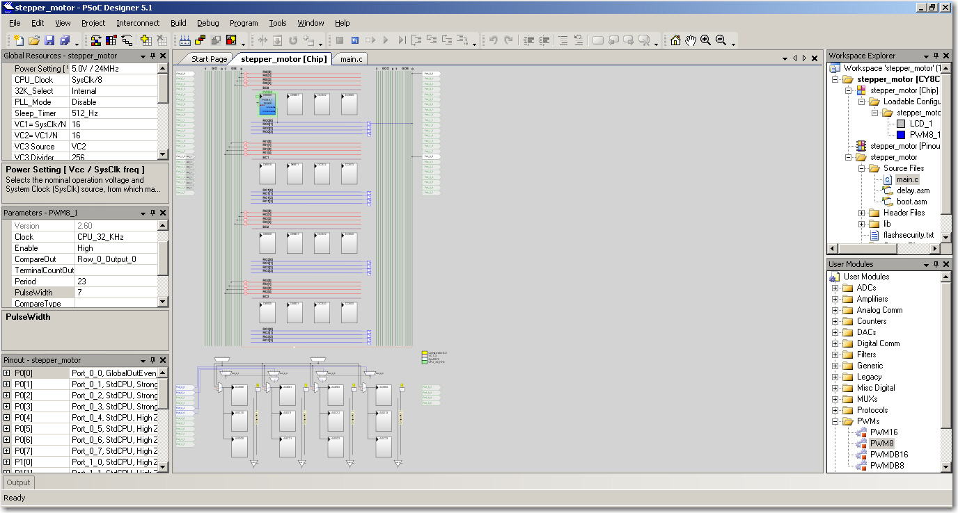
The picture showing you the properties window is where you set
properties for when PSOC starts up, for that module, and the
global chip properties.
In your case you will be changing PWM pulese dutry cycle with software
as well. In datasheet are functionb call you can use to write the compare
register which will change the duty cycle.
Regards, Dana.
- Mark as New
- Bookmark
- Subscribe
- Mute
- Subscribe to RSS Feed
- Permalink
- Report Inappropriate Content
The picture showing you the properties window is where you set
properties for when PSOC starts up, for that module, and the
global chip properties.
In your case you will be changing PWM pulese dutry cycle with software
as well. In datasheet are function call you can use to write the compare
register which will change the duty cycle.
Regards, Dana.
- Mark as New
- Bookmark
- Subscribe
- Mute
- Subscribe to RSS Feed
- Permalink
- Report Inappropriate Content
I have created :
void GenerateOneThirdDutyCycle(void)
{
/* set period to eight clocks */
PWM8_WritePeriod(199);
/* set pulse width to generate a 33% duty cycle */
PWM8_WritePulseWidth(200);
/* ensure interrupt is disabled */
PWM8_DisableInt();
/* start the PWM8! */
PWM8_Start();
}
but how can I include :
#include "PWM8_1.h"
always fail....
Should I include it manually ?
because I saw it's already there
- Mark as New
- Bookmark
- Subscribe
- Mute
- Subscribe to RSS Feed
- Permalink
- Report Inappropriate Content
I got :
!ERROR {linker} file 'main.o': undefined symbol '_PWM8_WritePeriod'
!ERROR {linker} file 'main.o': undefined symbol '_PWM8_DisableInt'
!ERROR {linker} file 'main.o': undefined symbol '_PWM8_Start'
!ERROR {linker} file 'main.o': undefined symbol '_PWM8_WritePulseWidth'
- Mark as New
- Bookmark
- Subscribe
- Mute
- Subscribe to RSS Feed
- Permalink
- Report Inappropriate Content
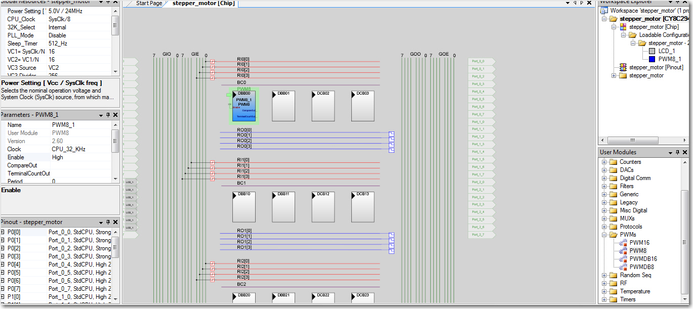
From the device editor screenshot (pwm3.jpg), it looks like the instance name of the PWM is PWM8_1. So, the APIs should be like this -
PWM8_1_WritePeriod, PWM8_1_DisableInt() and so on.
The APIs are always prefixed with its instance name.
- Mark as New
- Bookmark
- Subscribe
- Mute
- Subscribe to RSS Feed
- Permalink
- Report Inappropriate Content
Correct me if I'm wrong ....
How can I fix stall servo motor ? Thanks
/* Divide by eight function */
void GenerateOneThirdDutyCycle(void)
{
/* set period to eight clocks */
PWM8_1_WritePeriod(199);
/* set pulse width to generate a 33% duty cycle */
PWM8_1_WritePulseWidth(200);
/* ensure interrupt is disabled */
PWM8_1_DisableInt();
/* start the PWM8! */
PWM8_1_Start();
}
/* Divide by eight function */
void GenerateHalfDutyCycle(void)
{
/* set period to eight clocks */
PWM8_1_WritePeriod(14);
/* set pulse width to generate a 33% duty cycle */
PWM8_1_WritePulseWidth(15);
/* ensure interrupt is disabled */
PWM8_1_DisableInt();
/* start the PWM8! */
PWM8_1_Start();
}
- Mark as New
- Bookmark
- Subscribe
- Mute
- Subscribe to RSS Feed
- Permalink
- Report Inappropriate Content
How can I develope this spec?
Operating Speed (4.8V no load) : 0.131sec / 60 degrees
- Mark as New
- Bookmark
- Subscribe
- Mute
- Subscribe to RSS Feed
- Permalink
- Report Inappropriate Content
Please correnct me if I'm wrong,
I wanna move 180 degree , just alike car window wiper
/* Divide by eight function */
void GenerateOneThirdDutyCycle(void)
{
/* set period to eight clocks */
PWM8_1_WritePeriod(100);
/* set pulse width to generate a 33% duty cycle */
PWM8_1_WritePulseWidth(101);
/* ensure interrupt is disabled */
PWM8_1_DisableInt();
/* start the PWM8! */
PWM8_1_Start();
}
/* Divide by eight function */
void GenerateHalfDutyCycle(void)
{
/* set period to eight clocks */
PWM8_1_WritePeriod(1299);
/* set pulse width to generate a 33% duty cycle */
PWM8_1_WritePulseWidth(1300);
/* ensure interrupt is disabled */
PWM8_1_DisableInt();
/* start the PWM8! */
PWM8_1_Start();
}
/* Divide by eight function */
void GenerateZeroCycle(void)
{
/* set period to eight clocks */
PWM8_1_WritePeriod(1);
/* set pulse width to generate a 33% duty cycle */
PWM8_1_WritePulseWidth(2);
/* ensure interrupt is disabled */
PWM8_1_DisableInt();
/* start the PWM8! */
PWM8_1_Start();
}
main()
{
GenerateOneThirdDutyCycle();
Delay10msTimes(40);
GenerateHalfDutyCycle();
Delay10msTimes(40);
}
- Mark as New
- Bookmark
- Subscribe
- Mute
- Subscribe to RSS Feed
- Permalink
- Report Inappropriate Content
Hello Bianchi,
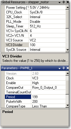
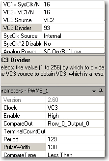
In order to obtain a 20 ms rate pulse, as mentioned by Dana - you can set use the VC1, VC2 and VC3 dividers. The divider properties should be -
VC1 = 6, VC2 = 4, VC3 source = VC2 and VC3 = 100 --> this will generate a 10 KHz (or 100 us) clock output from VC3 .
Setting your 8-bit PWMs input clock as VC3 and PWM Period as 199, gives a PWM period of 20 ms (= 100 uS * (199+1));
Now you have obtained the rate at which you want to send pulse to your servo. Next step would be to define the pulse width.
With a PWM compare type of "Less than" and a Pulse width of 10 - you should be able to get a 1 ms pulsewidth every 20 ms (PWM8 output will be high when the counter value is less than 10 and low otherwise ==> 10/200 * 20ms ==> 1 ms).
Similarly with a pulsewidth of 20, you get a 2 ms high pulse every 20 ms (20/200 * 20 ms ==> 2 ms)
So you don't have to change the period of the PWM, just changing the pulsewidth to these values will help you send the respective pulses to your servo.
Again, this PWM has a step size of 0.1 ms - if you want a finer step size; You can use the below parameters -
VC1, VC2 and VC3 source same, VC3 divider = 10 ==> VC3 clock period = 10 uS (your step size;
Use a PWM16 module and set the period as 2000 ( ==> 2000 * 0 uS = 20 ms)
Use pulsewidth as 200 for 2 ms and 100 for 1 ms; your step size is 0.01 ms - a finer step;
Hope this helps,
Regards,
MSUR
- Mark as New
- Bookmark
- Subscribe
- Mute
- Subscribe to RSS Feed
- Permalink
- Report Inappropriate Content
Bianchi,
Not sure why you are using a pulse width value higher than period value; As those statements, will result in your PWM output to be high all the time (if Compare type is selected as Less than) and also for a 8-bit PWM, you can only write a period/pulsewidth of value >255;
Now getting back to your requirement - Is it possible for you to send us the servo motor's datasheet? I can help you in getting the PWM configured properly for the same.
Regards,
MSUR
- Mark as New
- Bookmark
- Subscribe
- Mute
- Subscribe to RSS Feed
- Permalink
- Report Inappropriate Content
A correction in the above statement - it is period/pulsewidth value CANNOT be >255 for a 8-bit PWM; the lines below will result in an error -
/* set period to eight clocks */
PWM8_1_WritePeriod(1299);
/* set pulse width to generate a 33% duty cycle */
PWM8_1_WritePulseWidth(1300);
- Mark as New
- Bookmark
- Subscribe
- Mute
- Subscribe to RSS Feed
- Permalink
- Report Inappropriate Content
How can I develope this spec?
Operating Speed (4.8V no load) : 0.131sec / 60 degrees
- Mark as New
- Bookmark
- Subscribe
- Mute
- Subscribe to RSS Feed
- Permalink
- Report Inappropriate Content
If the requirement is to achieve 60deg revolution in 0.131 sec, then motor needs to be moved by one step in (0.786/TOTAL_MOTOR_STEPS) sec. So, configure a timer to generate this much delay and at each timer interrupt, update the motor step sequence.
Also, you have to tune the PWM duty cycle to acheive the required torque.
- Mark as New
- Bookmark
- Subscribe
- Mute
- Subscribe to RSS Feed
- Permalink
- Report Inappropriate Content
Please ignore my previous comment...I thought it is about stepper motor.
- Mark as New
- Bookmark
- Subscribe
- Mute
- Subscribe to RSS Feed
- Permalink
- Report Inappropriate Content
Hello Bianchi,
I believe the spec you are mentioning is the rate at which the servo turns.
We need the pulse timing details, for generating the PWM to hold the servo in a specific angle. If you let us know the datasheet or make of the servo you are using, it will be useful. For instance in the datatsheet of this servo, you can see the timing graph provided on Page 3. We would need a similar data for the servo you are using, to provide exact PWM configuration.
For the motor in the mentioned link, you can use the PWM settings i provided in my previous comments. And most of the servos, have pulse frequency of 50Hz (20 ms) only the pulse duration for a particular angle would be different across servos and that is what is required here for PWM setting.
Regards,
MSUR.
- Mark as New
- Bookmark
- Subscribe
- Mute
- Subscribe to RSS Feed
- Permalink
- Report Inappropriate Content
The operation of a PWM, Period, Compare Value, Duty Cycle occur as follows -
1) PWM is a down counter, starts by loading the period value you set in its properties
window or by using API. It counts down to 0, then reloads the period value, and keeps
repeating. So if you put in 1 Khz, period = 10, then the PWM produces a 1,000/10
rate = 100 Hz. Note the actual value you put in is N - 1, or 9.
2) The counter has attached to it a comparitor, that is always looking at value in counter, and
is comparing what the current counter value is against what you put in the compave value
properties, or by writing to the compare register. The comparitor logic is setable to <= or <,
so if set to <=, and your compare value setting is 4, then the compare output will be low as counter
counts down from 10 until it hits 4, at which time it goes high and stays there until PWM counter reloads
period value at end of cycle,, eg. 0 in the counter. So this is what you are doing when you set
compare value, you are setting duty cycle of the output. Again compare value is N - 1.
3) Your Servo has a relationship bbetween pulse width, eg. the compare output, and angle.
Typical servos are null (0 degrees) at 1.5 mS, at - 60 @ 1 mS, + 60 @ 2 mS.
Hope this helps.
Regards, Dana.
- Mark as New
- Bookmark
- Subscribe
- Mute
- Subscribe to RSS Feed
- Permalink
- Report Inappropriate Content
I can't find the datasheet, only get this one from the seller website :
Operating Speed : 0.13sec / 60 degrees (6.0V no load) Stall Torque : 13 kg-cm (180.5 oz-in) at 4.8V
- Mark as New
- Bookmark
- Subscribe
- Mute
- Subscribe to RSS Feed
- Permalink
- Report Inappropriate Content
- Mark as New
- Bookmark
- Subscribe
- Mute
- Subscribe to RSS Feed
- Permalink
- Report Inappropriate Content
I used this code, there's rotation but it's not 60 degree,
do I make a right code and right setting ?
thanks
void GenerateOneThirdDutyCycle(void)
{
/* set period to eight clocks */
PWM8_1_WritePeriod(10);
/* set pulse width to generate a 33% duty cycle */
PWM8_1_WritePulseWidth(11);
/* ensure interrupt is disabled */
PWM8_1_DisableInt();
/* start the PWM8! */
PWM8_1_Start();
}
/* Divide by eight function */
void GenerateHalfDutyCycle(void)
{
/* set period to eight clocks */
PWM8_1_WritePeriod(129);
/* set pulse width to generate a 33% duty cycle */
PWM8_1_WritePulseWidth(130);
/* ensure interrupt is disabled */
PWM8_1_DisableInt();
/* start the PWM8! */
PWM8_1_Start();
}