


- Mark as New
- Bookmark
- Subscribe
- Mute
- Subscribe to RSS Feed
- Permalink
- Report Inappropriate Content
Dear All:
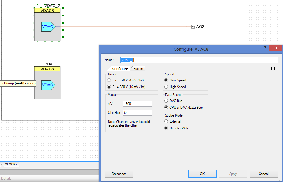
I am working a new design with two DACs (VDAC_1 and VDAC_2) . I attached some pictures describing the DAC configuration and PSOC system configuration. All the power for PSOC5 chip are 5V.
I am trying to configure the output to the maximun value of 4.080V but I only get 1.024V. The piece of code for set this value is:
VDAC_1_SetRange(VDAC_1_RANGE_4V);
VDAC_2_SetRange(VDAC_1_RANGE_4V);
VDAC_1_SetValue(0x0);
VDAC_2_SetValue(0xFF);
As it seems to be very symple according to the datasheet, I think I am missing something, can anyone tell me what else should I configure to get the output 4.080V?
Thanks in advance,
Joaquín.
- Labels:
-
PSoC 5LP
- Mark as New
- Bookmark
- Subscribe
- Mute
- Subscribe to RSS Feed
- Permalink
- Report Inappropriate Content
Circuit loading is causing your issue. Use an op-amp to buffer the voltage output.
- Mark as New
- Bookmark
- Subscribe
- Mute
- Subscribe to RSS Feed
- Permalink
- Report Inappropriate Content
Did you ..._Start() the VDAC?
- Mark as New
- Bookmark
- Subscribe
- Mute
- Subscribe to RSS Feed
- Permalink
- Report Inappropriate Content
VDAC_1_SetRange(VDAC_1_RANGE_4V);
VDAC_2_SetRange(VDAC_1_RANGE_4V);
VDAC_1_SetValue(0x0);
VDAC_2_SetValue(0xFF);
The second statement should be VDAC_2_SetRange(VDAC_2_RANGE_4V);
Also the 3 statement sets VDAC_1 to 0 V out, the 4'th to full scale once you correct
the second statement.
Regards, Dana
- Mark as New
- Bookmark
- Subscribe
- Mute
- Subscribe to RSS Feed
- Permalink
- Report Inappropriate Content
Thank you all for your reply.
Answering to your comments:
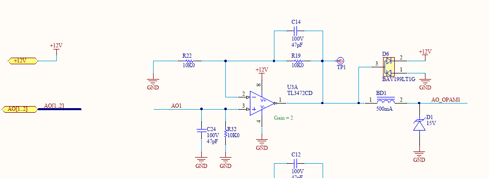
I attached the external (external to PSOC chip, I mean) circuitry at the output of the DACs. As you can see, I have an OA with gain of 2.
Yes, I Start de VDAC_1 & VDAC_2
Regarding the sentences, you are right Dana, It was an errata. I have corrected it but no 4.080V at the output:
VDAC_1_SetRange(VDAC_1_RANGE_4V);
VDAC_2_SetRange(VDAC_2_RANGE_4V);
VDAC_1_SetValue(0xFF);
VDAC_2_SetValue(0xFF);
Any other suggestion?
Thanks in advance,
Joaquin
- Mark as New
- Bookmark
- Subscribe
- Mute
- Subscribe to RSS Feed
- Permalink
- Report Inappropriate Content
- Mark as New
- Bookmark
- Subscribe
- Mute
- Subscribe to RSS Feed
- Permalink
- Report Inappropriate Content
Joaquin : Here is a program it sets the input of the Adc to 0V and max 4 volts . you need to jumper the P0-0 to P3-7 to get the voltage follower output to the input of the ADC. Press C on you terminal keyboard program such as PUTTY or some other terminal program for 0.0mv . Press S on your terminal program keyboard for max output. I have to ask why you didn't use a PSOC 5 op-amp for your follower. That's the best part of PSOC all of the components at your fingertips.
- Mark as New
- Bookmark
- Subscribe
- Mute
- Subscribe to RSS Feed
- Permalink
- Report Inappropriate Content
Thank you all.
I didn´t realize of the resistive output of the VDAC so, as soon as I removed the resistance out of the PSOC chip, it started to work normally.
Thank you again for your support. This kind of help makes life a little bit easier.
Regards,
Joaquín.
- Mark as New
- Bookmark
- Subscribe
- Mute
- Subscribe to RSS Feed
- Permalink
- Report Inappropriate Content
Hi all,
I had the same issue because I placed a 20 k resistor at the output of the DAC as a pull-down for the OP-Amp non-inverting input on which I connected the DAC.
I was reading 2 V when writing 0xFF with Set_Value() command.
These post have been quite useful for me.
Thank you
David