

- Mark as New
- Bookmark
- Subscribe
- Mute
- Subscribe to RSS Feed
- Permalink
- Report Inappropriate Content
Hi,
I have CY8CKIT-059 Prototyping kit and I downloaded CE210741 example code for evaluation of UART component. As is, the generated code does not run as stand alone application. It does not run without the USB connection to KitProg and also does not run without the KitProg attached to the target board. It works though with the USB connection to the kit but it is not what what I need. I need to take it away from the computer, attach it to a serial device working as terminal and demonstrate it works like "Blinky" the application already installed when I purchased the kit.
So I have a simple question: UART Component - Can it be used in stand-alone applications?
Looking forward to a dialog.
Best regards.
Solved! Go to Solution.
- Mark as New
- Bookmark
- Subscribe
- Mute
- Subscribe to RSS Feed
- Permalink
- Report Inappropriate Content
When KitProg is connected to the board, you cannot use P17.6 and P12.7 for the UART. These two pins are connected to the KitProg (via R22/R23). So then KitProg is powered down (by removing its USB cable), it will pull the pins low (integrated ESD diodes). This means that on RX most likely a BRK will be received (everything 0), and nothing can be observed on TX since it will be 0 all the time too.
Route the UART to other pins (e.g. P2.6 / P2.7 are unused) and connect the FTDI there.
The example you are using is designed to be used with the KitProg USB-UART bridge, so the UART is routed to the appropriate pins (which is done automagically by Creator).
- Mark as New
- Bookmark
- Subscribe
- Mute
- Subscribe to RSS Feed
- Permalink
- Report Inappropriate Content
The PSoC -059 prototype board gets its power from the USB interface (5V). When you remove the kitprog and power the board it will run as you require. Only problem is: The RS232 signal is at +- 12V level, so you will need a level converter chip (as MAX232) to connect the PSoC to your terminal.
Bob
- Mark as New
- Bookmark
- Subscribe
- Mute
- Subscribe to RSS Feed
- Permalink
- Report Inappropriate Content
Dear Sir,
I have all power requirements satisfied already from an external power source.
I have the signal levels sorted out.
I have tested the example and it is working while I have both KitProg and the USB connected to the target.
I have tested the example as stand-alone and is not working.
All my bench experience lead me to think that the component UART has a bug. I may be wrong but I'm listening if anyone would try to communicate back to me.
So, can a paying costumer use the component reliably?
If there is a problem has it been acknowledged and is it somebody working for a fix?
I would hate after so much time and energy invested in this PSoC product you have, a bad communication to be a show stopper.
Again, can a paying costumer use the UART component reliably in stand alone applications?
Thanks.
- Mark as New
- Bookmark
- Subscribe
- Mute
- Subscribe to RSS Feed
- Permalink
- Report Inappropriate Content
The UART component works reliable and there are no known bugs with that component.
As I said in my last post, your problem will be the standard UART voltage which will require a voltage converter to match the needed standards.
In the -059 prototype kit the interface is made by an UART to USB bridge which will work only with PCs, You will need a voltage shifter. There are special cables which include such a level shifter. Did you check the requirements of your connected serial device? What does it say??
Bob
- Mark as New
- Bookmark
- Subscribe
- Mute
- Subscribe to RSS Feed
- Permalink
- Report Inappropriate Content
bob.marlowe wrote:
The UART component works reliable and there are no known bugs with that component.
I claim I just found a bug. Did anyone try to replicate the failure?
As I said in my last post, your problem will be the standard UART voltage which will require a voltage converter to match the needed standards.
[snip]
You will need a voltage shifter. There are special cables which include such a level shifter. Did you check the requirements of your connected serial device? What does it say??
Please don't insult my intelligence: If don't have the required conditions to meet the standards, how is it possible that it works with the KitProg and the USB cable attached to computer?
In the -059 prototype kit the interface is made by an UART to USB bridge which will work only with PCs
Bob
While I completely understand that, the whole purpose is to get the chip on a PCB and have confidence that it will work with any components in a stand-alone situation.
-059 kit offers the chance to evaluate any component and the PCB encourages the use of head terminals including the scenario that the power can be applied externally. I understand it is my job not to fry the kit.
The UART datasheet tells:
Bootloader Support
The UART Component can be used as a communication Component for the Bootloader.
Bootloader support does not mean dependency on it. UART should (must also) work without bootloader interaction. One good working example is the USBFS which works like a charm with or without KitProg being connected to the target. That example works. CE210741 example does not. Hence my claim that I found a bug with the UART component.
Please ask someone with a superior level of support to verify my claim. I trust that would not be a problem for you to power externally the kit with 5V and use a TTL to USB gimmick to connect to a terminal. Other than the Pin allocation, no other change needs to be done to the example CE210741. The try with then without KitProg. Please just try it.
Best regards.
- Mark as New
- Bookmark
- Subscribe
- Mute
- Subscribe to RSS Feed
- Permalink
- Report Inappropriate Content
Please, calm down. Stay polite.
First, we are all volunteers here - this is a developer forum, not the Cypress support hotline. Second, Bob has probably like 10 years of experience with the PSoC chips. He knows more than you about them.
Third: when using a component (or software) with a good track record of reliability and quality, its good engineering practice not to assume that it is faulty.
So please state your actual problem more clearly:
- what does your program / project actually do?
- which connections do you have to the -059 board (both when connected to a computer, and when not)?
- which behavior do you expect, and what do you observer instead?
- how do you determine that it is the UART component that is at fault? (did you look with a scope at the output signals)
- how do you determine that it is not your code that is wrong? (e.g. use LEDs or other observable behavior to see that it is running as intended)
- what did you already do to fix the problem?
Just like Bob, I have used the UART component in multiple project, and can ensure you that it indeed runs standalone.
But: did you actually _read_ the PDF for CE210741? It explicitly mentions using the USBUART of the Kitprog serving as bridge between the PSoC and the computer (under 'Software setup'). This naturally does not work without Kitprog. You need to route the UART to other pins.
- Mark as New
- Bookmark
- Subscribe
- Mute
- Subscribe to RSS Feed
- Permalink
- Report Inappropriate Content
I suspect you will have a difficult time finding someone capable of providing a superior level of support than Bob Marlowe.
I can refute your claim of a bug in the UART component to the extent that for the past 18 months I have been using the CY8CKIT-059 as a stand alone module that plugs into my development boards powered at 5V. I use the UART component both as a debug port via an FTDI smart cable and to communicate with a WiFi module. It works fine. I have observed no bugs.
I have used the UART component successfully in four devices:
CY8C5888LTI-LP097 in the CY8CKIT-059
CY8C5868AXI-LP035 in the CY8CKIT-050
CY8C5868LTI-LP039
CY8C5667AXI-LP040
Have you managed to get the -059 to do anything as a stand alone module?

- Mark as New
- Bookmark
- Subscribe
- Mute
- Subscribe to RSS Feed
- Permalink
- Report Inappropriate Content
Hi,
I will describe my hardware setup.
-59 kit plugged into a development board which has only the role of delivering the 5V power supply and taking the communication pins. That means the only pins connected are:
- the power pins
- Rx and Tx pins conected to a FTDI TTL to USB module like in this picture:
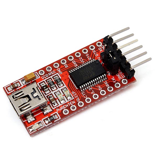
This module is connected to a Terminal program running into a PC.
From a different computer where I run PSoC Creator I run an USB cable to the programmer of -059 kit.
That's all, everything is the bare minimal hardware setup.
Moments ago I started New Project -> chose CY8C5888LTI-LP097 as target -> From example -> UART Full Duplex and I had all project available in PSoC Creator.
Then I allocated the pins for components: LED - P2.1, SW2 - P2.2, Rx - P12.6, Tx - P12.7.
No other changes from the vanilla component example.
Built the project and programmed the target.
With the USB cable still connecting the PSoC Creator and the KitProg, the application works as intended: all characters I type on Terminal PC are returned back.
When I disconnect the USB cable from the KitProg, with the board still powered, the characters transmitted from terminal are not transmitted back. The blue LED on the kit turns ON signaling there was an error.
Now you have the full description of what I have and what I do and why I am telling the UART example is not a stand alone application. Not in my case, not on my bench. Since I have no other contribution to the software other than allocating the pins, I don't see where I failed.
For your enjoyment I attach the archive with the example.
As a final observation, as brock said he was working the last 18 months on the same kit, I noticed that the date on "common.h", "cyapicallbacks.h", "debug.c" and "main.c" is August 13, 2018. Is it possible brock that somehow "corrupt" files were submitted into repository on that date and you were having no problems because you used some older files? Just a thought...
Here it goes the archived project.
- Mark as New
- Bookmark
- Subscribe
- Mute
- Subscribe to RSS Feed
- Permalink
- Report Inappropriate Content
P12.6 and P12.7 are routed to the KitProg. Since you did not tell otherwise, I assume the -059 board is still complete (KitProg attached to the board).
Where do you connect the FTDI board to? Where does this blue LED come from that signals an error? Is it driven by your code?
- Mark as New
- Bookmark
- Subscribe
- Mute
- Subscribe to RSS Feed
- Permalink
- Report Inappropriate Content
One additional note: even when your FTDI board is connected to the correct pins - when they are also handled by the KitProg, not powering the latter one might just pull the pins low.
- Mark as New
- Bookmark
- Subscribe
- Mute
- Subscribe to RSS Feed
- Permalink
- Report Inappropriate Content
To eliminate the common bugs:
Did you cross Rx and Tx between PSoC and the "development board"
Can you please post your complete project or a shortened version that shows the error so that we all can have a look at all of your settings. To do so, use
Creator->File->Create Workspace Bundle (minimal)
and attach the resulting file.
Bob
- Mark as New
- Bookmark
- Subscribe
- Mute
- Subscribe to RSS Feed
- Permalink
- Report Inappropriate Content
bob.marlowe wrote:
To eliminate the common bugs:
Did you cross Rx and Tx between PSoC and the "development board"
Yes, Rx1 to Tx2 and Tx1 to Rx2. The mere fact that it works when USB was attached to programmer tells me that the connections between the target and FTDI board are correct.
Can you please post your complete project or a shortened version that shows the error so that we all can have a look at all of your settings. To do so, use
Creator->File->Create Workspace Bundle (minimal)
and attach the resulting file.
Bob
Here it is as attachment and if I may add, there is not a thing that I changed from the example. Right now I'm thinking that I am dealing with corrupted files that were downloaded through Update Manager. May I just delete all examples and download them again? How?
- Mark as New
- Bookmark
- Subscribe
- Mute
- Subscribe to RSS Feed
- Permalink
- Report Inappropriate Content
user_78878863 wrote:
P12.6 and P12.7 are routed to the KitProg. Since you did not tell otherwise, I assume the -059 board is still complete (KitProg attached to the board).
Where do you connect the FTDI board to? Where does this blue LED come from that signals an error? Is it driven by your code?
I prefer to take testing in 2 stages: 1st to have only the USB cable removed from programmer, 2-nd Kitprog removed from the target.
1. Right now being in the stage 1, kitprog is still attached to the target, FTDI board is connected to pins12.6 and 12.7.
2. The blue LED is on board LED (target board) connected to P2.1. This LED is driven by the code (CE210741 example). I have not a single line added nor change from the initial code. Shortly I will attach the bundle as Bob requested and you can examine it if you wish.
One additional note: even when your FTDI board is connected to the correct pins - when they are also handled by the KitProg, not powering the latter one might just pull the pins low.
I probed the pins with a scope (stage 1 of testing) and there is a healthy High state. But I got your point and thanks; it maybe an issue when I get to stage 2.
- Mark as New
- Bookmark
- Subscribe
- Mute
- Subscribe to RSS Feed
- Permalink
- Report Inappropriate Content
When KitProg is connected to the board, you cannot use P17.6 and P12.7 for the UART. These two pins are connected to the KitProg (via R22/R23). So then KitProg is powered down (by removing its USB cable), it will pull the pins low (integrated ESD diodes). This means that on RX most likely a BRK will be received (everything 0), and nothing can be observed on TX since it will be 0 all the time too.
Route the UART to other pins (e.g. P2.6 / P2.7 are unused) and connect the FTDI there.
The example you are using is designed to be used with the KitProg USB-UART bridge, so the UART is routed to the appropriate pins (which is done automagically by Creator).
- Mark as New
- Bookmark
- Subscribe
- Mute
- Subscribe to RSS Feed
- Permalink
- Report Inappropriate Content
Phase 1 is now a success. Without USB connection from Creator to KitProg the characters I transmit are received and displayed on Terminal. I have changed the input pin Rx from HZ to Pull Up and it worked on the same pin allocation P12.6 and 12.7. Thanks for the help.
I will separate the KitProg from the target to get in phase 2 of my testing.
I have a question though: after programing the target, is there a verify sequence? To make sure the target was programmed correctly.
- Mark as New
- Bookmark
- Subscribe
- Mute
- Subscribe to RSS Feed
- Permalink
- Report Inappropriate Content
I see now that the phase 2 (as I call it) of my tests has no chance to pass because the tracks Rx and Tx from programmer and the target are severed after breaking out the programmer board.
Anyway, I am satisfied that I found the cause of the failure and thank you all for the assistance in debugging.
- Mark as New
- Bookmark
- Subscribe
- Mute
- Subscribe to RSS Feed
- Permalink
- Report Inappropriate Content
Sorry I forgot to answer a question, yes I do have several projects that run stand alone.
One of my favorites is http://www.cypress.com/documentation/component-datasheets/full-speed-usb-usbfs
This UART works stand alone and it is amazing.
- Mark as New
- Bookmark
- Subscribe
- Mute
- Subscribe to RSS Feed
- Permalink
- Report Inappropriate Content
Hendrik, brock
Thank you both very much for standing by me! That was very kind and made me feel quite happy!
Thanks, Bob